Transcription of The Model T Ignition Coil - funprojects.com
1 Part 1 in a Three-part Series that first appeared in Volume 34 of the Vintage Ford MagazineThe Model T Ignition CoilPart I: The Ford/K-W Ignition Company StoryBy Trent Boggess and Ronald Patterson All in all, the magneto commutator coil units supplied by the Ford Motor Companydid a better and more creditable job than anything offered by the accessory firms. - Reminiscences of MaherWhat could be more characteristic of aModel T Ford than a box containing four vibratorignition coils on the dash? Coils that alwayssound like a nest full of angry bees.
2 Coils thatsometimes will reward the Model T driver with a free start if when the engine was turned off, oneof the pistons stopped just after top-dead centeron the compression vibrator Ignition coil system did notoriginate with the Model T, nevertheless; theModel T was its most famous application. In thisand the following two articles we will attempt tocomprehensively present the story of the Model Tignition coil. Part 1 presents a brief history of theModel T Ignition coil beginning with the evolu-tion of the timer and vibrator coil Ignition systemin early Ford design automobiles.
3 We will also goon to describe the various brands of Ignition coilsused on Model Ts during the first five years ofproduction and some of the problems that devel-oped with these Part 2 we will present the story of how Fordcame to standardize on the Ignition coil designedby Joseph Williams of the K-W Ignition Companyin 1913 and the subsequent business relationshipbetween Ford and K-W Ignition . Finally, in Part3, we will attempt to construct an anthology of thevarious types of post-1913 Ignition coils used onthe Model T, describing their features androughly dating their of the thorniest problems in the devel-opment of the internal combustion engine werethe issues of carburetion and Ignition .
4 The firstinvolved getting the right mixture of highly com-bustible fuel and air into the cylinders and thesecond involved igniting it at just the right mo-ment. Henry Ford s first car, the 1896 Quadricy-cle, took a brut-force direct approach to solvingboth of these problems. Carburetion wasachieved by the expedient of a needle valve thatallowed gasoline to drip into the intake manifoldat a more or less controlled rate. Once in themanifold, the gas would be swept up and drawninto the cylinders by the air rushing through themanifold on the intake stroke.
5 Once in the cylin-ders, the air-fuel mixture was compressed andmade ready for Ignition . Again Ford adopted adirect approach to solving this problem. The mix-ture was ignited by a technique known as makeand break. This simple Ignition system hadbeen in use in stationary gas engines for a num-ber of years and was later used on several earlyautomobiles. Two electrodes, or contacts, wereattached inside the cylinder head, one insulatedand fixed, and the other one moveable andgrounded. Electricity from a battery passed firstthrough a simple electrical coil (that both createdan electrical resistance and intensified thespark), then through the contacts to the groundand finally back to the battery to complete thecircuit.
6 When the two contacts were separated bysome mechanical means (in Ford s case, a boltattached to the top of the piston would strike themoveable contact just before the piston reachedthe top of its stroke), a spark occurred that ig-nited the fuel-air mixture within the rough-but-ready solution to the ignitionproblem had one serious drawback. The timingof the Ignition was fixed by the bolt on the pistonat about 10 degrees before top dead center. Thespark could not be retarded for starting the en-gine nor advanced to increase its speed.
7 [In laterdevelopment of the make-and-break system forstationary engines and early automobiles, thecontacts were in the cylinder, but the mechanismfor opening and closing the contacts were placedoutside the cylinder. This allowed for a means foradvancing and retarding the spark.] All in all,Henry Ford s primitive Ignition system com-bined with its equally crude carburetor worked,but it severely restricted the performance andrange of operation of the engine on his first better system was needed. Fortunately forHenry Ford, he made the acquaintance of Ed-ward S.
8 Huff and was able to enlist him in Ford sautomobile development Henry Ford s many, early lieuten-ants, none was more talented in the field ofelectricity than Ed Huff. One early associate15recalled Ed wasquite a genius. Hewas a mechanicalgenius in puttingthings together. Hehad quite a yen forelectricity and gearsand things of thatkind. When it cameto the problem of ig-nition He was justthe type of fellowwho was needed onthat job. In early 1902while Ford was de-signing and build-ing what wouldbecome the famous 999 race car, hedelegated the taskof designing of theignition system toEd Huff.
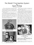
9 Huff aban-doned the make andbreak Ignition sys-tem in favor of a jump spark jumpspark Ignition sys-tem was not a newdevelopment, and infact had been in usefor nearly fortyyears. The French-man Lenoir, who isPhoto 1:A simple vibrator coil Ignition system showing the layout of thecredited with build-commutator, coil and wiring. Illustration from Victor PageThe Model T Ford Car,ing the first success-1917 Edition, Norman W. Henley Publishing Co, NY, 1917, p. engine, used something like it in hisengines as early as jump spark system employed a sparkplug, a commutator that timed the spark to thecylinder, a battery to serve as a source of current,and a vibrator coil.
10 (See Photo 1). The theory ofthe vibrator coil was quite complex for the consisted of two circuits of wires wound aroundan iron core. (See Photo 2). The primary circuitconsisted of a number of turns of fairly heavygauge wire. When current from the batteryflowed through this circuit it served to turn theiron core into an electromagnet. The seondarycircuit consisted of a very large number of turnsof a very fine wire wrapped around the same ironcore. This secondary circuit was connected to thespark plug.