Transcription of The NorCal Sierra: An 80-15 M CW Transceiver
1 The NorCal sierra : An 80-15 M CW TransceiverMost home-built QRP transceivers cover a single band, for good reason: complexity of the circuit and physical layout can increase dramatically when two or more bands are covered. This holds for most approaches to multiband design, including the use of multipole switches, transverters and various forms of electronic If the designer is willing to give up instant band switching, then plug-in band modules can be used. Band modules are especially appropriate for a Transceiver that will be used for extended portable operation, for example: back-packing.
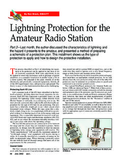
2 The reduced circuit complexity improves reliability, and the extra time it takes to change bands usually isn't a problem. Also, the operator need take only the modules needed for a particular sierra Transceiver shown in Fig uses this technique, providing coverage of all bands from 80 through 15 m with good performance and relative The name sierra was inspired by the mountain range of the same name a common hiking destination for West Coast QRPers. The Transceiver was designed and built by Wayne Burdick, N6KR, and field tested by members of NorCal , the Northern California QRP Chapter 17 - Receivers, Transmitters, Transceivers and Projects: The NorCal sierra : An 80-15 M CW Transceiver - Page 1Th ARRL H db k CD Vi3 0 Ci ht (C) 1998 b Th AiR di R lLI Fig The sierra Transceiver .
3 One band module is plugged into the center of the main PC board; the remaining boards are shown to the left of the rig. Quick-release latches on the top cover of the enclosure make it easy to change bands. FeaturesOne of the most important features of the sierra for the portable QRP operator is its low current drain. Because it has no relays, switching diodes or other active band-switching circuitry, the sierra draws only 30 mA on Another asset for field operation is the sierra 's low-frequency VFO and premixing scheme, which provides 150 kHz of coverage and good frequency stability on all receiver is a single-conversion superhet with audio-derived AGC and RIT.
4 It has excellent sensitivity and selectivity, and will comfortably drive a speaker. Transmit features include full break-in keying, shaped keying and power output averaging 2 W, with direct monitoring of the transmitted signal in lieu of sidetone. Optional circuitry allows monitoring of relative power output and received signal , the sierra is quite compact the enclosure is inches (HWD) yet there is a large amount of unused space both inside and on the front and rear panels. This results from the use of PC board-mounted controls and connectors. The top cover is secured by quick-release plastic latches, which provide easy access to the inside of the enclosure.
5 Band changes take only a few DescriptionFig is a block diagram of the sierra . The diagram shows specific signal frequencies for operation on 40 m. Table provides a summary of crystal oscillator and premix frequencies for all bands. The schematic is shown in Fig See Tabl e for band-module component values. On all bands, the VFO range is MHz to MHz. The VFO tunes "backwards": At the low end of each band, the VFO frequency is MHz. U7 is the premixer and crystal oscillator, while Q8 buffers the premix signal prior to injection into the receive mixer (U2) and transmit mixer (U8).A low-pass filter, three band-pass filters and a premix crystal make up each band module.
6 To make the schematic easier to follow, this circuitry is integrated into Fig , rather than drawn separately. J5 is the band module connector (see the note on the schematic).The receive mixer is an NE602, which draws only mA and requires only about V (P-P) of oscillator injection at pin 6. An L network is used to match the receive mixer to the first crystal filter (X1-X4). This filter has a bandwidth of less than 400 Hz. The single-crystal second filter (X5) removes some of the noise generated by the IF amplifier (U7), a technique W7 ZOI This second filter also introduces enough loss to prevent the IF amplifier from overdriving the product detector (U4).
7 The output of the AF amplifier (U3) is dc-coupled to the AGC detector. U3's output floats at Vcc/2, about 4 V, which happens to Chapter 17 - Receivers, Transmitters, Transceivers and Projects: The NorCal sierra : An 80-15 M CW Transceiver - Page 2Th ARRL H db k CD Vi3 0 Ci ht (C) 1998 b Th AiR di R lLI be the appropriate no-signal AGC voltage for the IF amplifier when it is operated at 8 V. C26, R5, R6, C76 and R7 provide AGC loop filtering. Like all audio-derived AGC schemes, this circuit suffers from pops or clicks at signal monitoring is achieved by means of a separate MHz oscillator for the transmitter; the difference between this oscillator and the BFO determines the AF pitch.
8 Keying is exponentially shaped, with the rise time set by the turn-on delay of transmit mixer U8 and the fall time determined by C51, in the emitter of driver Q6. Fig Block diagram of the sierra Transceiver . Three different-shaped symbols are used to show transmit, receive and common blocks. Those blocks with an asterisk (*) are part of the band module. Signal frequencies shown are for 40 m; see Table for a list of crystal oscillator and premix frequencies for all 17 - Receivers, Transmitters, Transceivers and Projects: The NorCal sierra : An 80-15 M CW Transceiver - Page 3Th ARRL H db k CD Vi3 0 Ci ht (C) 1998 b Th AiR di R lLI C57, C58 Polystyrene, 1200 pF, 5%.
9 D6, D10 1N5817, 1N5819 or similar .D7 36 V, 1 W Zener diode (Mouser 333-1N4753A).D8 MV2104 varactor diode, or , J2 PC-mount stereo jack with switch (Mouser 161-3500).J3 dc power jack (Mouser 16PJ031).J4 PC-mount BNC jack (Mouser 177-3138).J5 50 PIN, dual-row edgeboard connector with spacing (Digi-Key S5253-ND).L10, L11 18 H; 18 t #28 enameled wire on an FT-37-61 Miniature RFC, 15 H (Mouser, 43LS185).L7 19 H; 58 t #28 enameled wire on a T-68-7 U310, J310, 2N4416 or other high-transconductance , R8 PC-mount 1-k pot (Mouser 31CW301).R14, R101 500 trimmer (Mouser 323-4295P-500).
10 R17 PC-mount 10-k pot (Mouser 31CW401).RFC1 H; 8 t #26 enameled wire on an FT-37-61 7 H; 4 t #26 enameled wire on an FT-37-43 34 H; 9 t #26 enameled wire on an FT-37-43 Miniature RFC, 1 mH (Mouser 43LS103).S1, S2 SPDT, PC mount, right angle toggle switch with threaded bushing. C&K 7101 SDAV2QE is used in the kit; Digi-Key CKN1059-ND will work but does not have a threaded Primary: 12 t #26 enameled wire; secondary: 3 t on an FT-37-43 LM358N dual op-amp , U4, U7, U8 NE602AN mixer-oscillator LM386N-1 audio amplifier MC1350P IF amplifier LM393N dual comparator 8 V regulator, TO-92 package (Digi-Key AN78L08-ND).