Transcription of THE PIN DIODE CIRCUIT DESIGNERS’ HANDBOOK - QSL.net
1 Microsemi 580 Pleasnt Street, Watertown, MA 02472 Tel. (617) 926-0404 FAX. (617) 924-1235 Microsemi-WatertownTHE PIN DIODE CIRCUIT DESIGNERS HANDBOOKThe PIN DIODE CIRCUIT Designers HANDBOOK was written for the microwave and RF DesignEngineer. Microsemi Corp. has radically changed the presentation of this PIN DIODE applicationsengineering material to increase its usefulness to microwave and RF CIRCUIT Designers. A major part ofthis HANDBOOK is devoted to the basic CIRCUIT applications of this unique July of 1992, Microsemi Corporation, headquartered in Santa Ana, California, purchasedUnitrode Semiconductor Products Division (SPD), in Watertown, Massachusetts, from UnitrodeCorporation.
2 This new Microsemi division , Microsemi (MSC-WTR), is committed tothe same high standards of quality products and continuous customer service improvements that havebeen the foundation of Microsemi s thirty year Corporation makes no representation that the use or interconnection of the circuitsdescribed herein will not infringe on existing or future patent rights, nor do the descriptions containedherein imply the granting of license to make, use or sell equipment constructed in accordance therewith. 1998, by Microsemi Corporation. All rights reserved. This book, or any part or parts thereof, must not be reproduced in any formwithout permission of the copyright : The information presented in this HANDBOOK is believed to be accurate and reliable.
3 However, no responsibility is assumed byMicrosemi Corporation for its use. Powermite is a registered trade mark of Microsemi #98=WPD-RDJ007 Microsemi 580 Pleasnt Street, Watertown, MA 02472 Tel. (617) 926-0404 FAX. (617) 924-1235 Microsemi 580 Pleasnt Street, Watertown, MA 02472 Tel. (617) 926-0404 FAX. (617) 924-1235 PrefaceThis PIN DIODE CIRCUIT Designers HANDBOOK was written for the microwave and RF Design Engineer. Amajor part of this HANDBOOK is devoted to the basic CIRCUIT applications of this unique device. In eachchapter, a CIRCUIT function is treated in detail followed by specific selected applications. For example, inChapter 2, the common PIN DIODE switch configurations are presented, followed by sections comparingthose features of PIN DIODE switch designs for unique to high power microwave switches and high powerlower frequency (RF-band) are many unique market applications, such as the wireless Communications Market, where newnetwork applications and system designs outpace the component technology needed to support , there are sections that discuss the unique CIRCUIT functional requirements appropriate to thesenewer market applications.
4 wireless Telecommunications power control circuits are discussed in terms ofthe role pin diodes play in providing low distortion, low Bit-Error-Rate (BER) performance for RFChannel components, particularly in next generation multimedia systems such as PCS and , the characteristics of high power HF Band switches are treated in detail as well as those ofswitches designed for Magnetic Resonance Imaging (MRI) appendix on distortion in PIN DIODE Switches and Attenuators has been included, because of theincreased importance of this parameter to RF Channel performance of wireless Communications subject of driver circuits for PIN DIODE switches and Attenuator circuits is always relevant to anypractical component design, and thus has been included in a separate DIODE Physics topics, such as PIN DIODE forward and reverse bias operating characteristics andequivalent circuits, stored charge and lifetime, distortion and non-linearity, and thermal impedance.
5 Arecontained in specific appendices for supplementary and reference hope that the organization of this material will be found useful by CIRCUIT and system designers, forwhom this HANDBOOK was comments, additions, or deletions would be E. Doherty, Jr. D. Joos MAMicrosemi 580 Pleasnt Street, Watertown, MA 02472 Tel. (617) 926-0404 FAX. (617) 924-1235 Microsemi 580 Pleasnt Street, Watertown, MA 02472 Tel. (617) 926-0404 FAX. (617) 924-1235 THE PIN DIODE CIRCUIT DESIGNERS HANDBOOKCONTENTSCHAPTER ONEPIN DIODE GENERAL DESCRIPTIONCHAPTER TWOPIN DIODE RF SWITCHESCHAPTER THREEPIN DIODE RF ATTENUATORSCHAPTER FOURPIN DIODE RF MODULATORSCHAPTER FIVEPIN DIODE RF PHASE SHIFTERSCHAPTER SIXPIN DIODE CONTROL CIRCUITS FOR WIRELESSCOMMUNICATION SYSTEMSCHAPTER SEVENPIN DIODE CONTROL CIRCUITS FOR HF BANDINDUSTRIAL APPLICATIONSCHAPTER EIGHTPIN DIODES FOR MAGNETIC RESONANCEAPPENDIX APIN DIODE PHYSICSAPPENDIX BA COMPARISON OF PIN DIODE & RECTIFIERDIODES MPD 101 AAPPENDIX CTHE USE OF LOW DISTORTION PIN DIODE SWITCHESIN DIGITAL COMMUNICATIONS LINKS MPD 102 AAPPENDIX DPIN DIODE DRIVER
6 CIRCUITSAPPENDIX EPIN DIODE DISTORTIONAPPENDIX FPIN DIODE RADIATION DETECTORSAPPENDIX GMISCELLANEOUS FORMULAE AND DATAAPPENDIX HSURFACE MOUNT CRITERIAAPPENDIX IREFERENCESM icrosemi 580 Pleasnt Street, Watertown, MA 02472 Tel. (617) 926-0404 FAX. (617) 924-1235 CHAPTER - 1 PIN DIODE GENERAL DESCRIPTIONM icrosemi 580 Pleasant St., Watertown, MA 02472 Tel. (617) 926-0404 Fax. (617) 924-12352 NOTESM icrosemi 580 Pleasant St., Watertown, MA 02472 Tel. (617) 926-0404 Fax. (617) 924-12353 PIN DIODE GENERAL DESCRIPTIONThis chapter presents a general overview of PIN DIODE operating characteristics to form an adequate basisfor the subsequent chapters on the various PIN DIODE functional circuits.
7 Supplemental material on PIND iode Physics is included in the Appendices section of the microwave PIN DIODE is a semiconductor device that operates as a variable resistor at RF andMicrowave frequencies. A PIN DIODE is a current controlled device in contrast to a varactor DIODE which isa voltage controlled device. Varactors diodes are design with thin epitaxial I-layers ( for a high Q in thereverse bias) and little or no concern for carrier lifetime ( Stored Charge).When the forward bias controlcurrent of the PIN DIODE is varied continuously, it can be used for attenuating, leveling, and amplitudemodulating an RF signal. When the control current is switched on and off, or in discrete steps, the devicecan be used for switching, pulse modulating, and phase shifting an RF signal.
8 The microwave PIN DIODE 'ssmall physical size compared to a wavelength, high switching speed, and low package parasiticreactances, make it an ideal component for use in miniature, broadband RF signal control circuits. Inaddition, the PIN DIODE has the ability to control large RF signal power while using much smaller levels ofcontrol pin diodes offer a unique highly reliable package due to voidless construction,metallurically bonded pin structure, and an extremely rugged SOGO surface passivation. SOGO passivated devices may be driven into reverse voltage breakdown without the reverse voltage characteristiccollapsing. Microsemi pin diodes offer significant electrical and thermal advantages compared to PINdiodes manufactured by other suppliers.
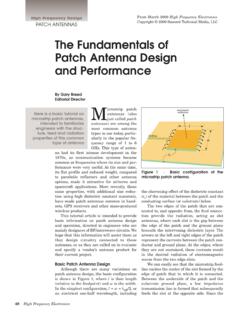
9 The Microsemi PIN DIODE is generally constructed using a PINchip that has a thicker I-region, larger cross sectional area and longer carrier lifetime for the same basicelectrical characteristics of series resistance (RS), and capacitance (CT). This results in pin diodes thatproduce lower signal distortion at all frequencies and power levels as well as devices that are capable ofhandling greater average and peak power than those manufactured by conventional techniques. Inaddition, since there are no ribbons or wires within the Microsemi s package, large surge currents may besafely handled and the parasitic resistance and inductance are minimized. ( a ) Cross Section of ( b ) Forward Bias ( c ) Reverse Bias Basic PIN DIODE Equivalent CIRCUIT Equivalent CIRCUIT Figure PIN DIODE and the Corresponding Equivalent CircuitsA drawing of a PIN DIODE chip is shown in Figure (a).
10 The performance characteristics of the PINdiode depend mainly on the chip geometry and the processed semiconductor material in the intrinsic or I -region, of the finished DIODE . When the DIODE is forward biased, holes and electrons are injected into theMicrosemi 580 Pleasant St., Watertown, MA 02472 Tel. (617) 926-0404 Fax. (617) 924-12354I-region. This charge does not recombine instantaneously, but has a finite lifetime ( ) in the I-region. Ifthe PIN DIODE is reverse biased , there is no stored charge in the I-region and the device behaves like aCapacitance (CT) shunted by a parallel resistance (RP). These equivalent CIRCUIT parameters are defined inthe section below.