Transcription of The process design of gold leaching and carbon-in-pulp ...
1 13 The Journal of The South African Institute of Mining and MetallurgyJANUARY/FEBRUARY 1999 IntroductionAssuming that a gold ore has been effectivelyground to ensure maximum economicliberation of gold , the circuits that will havethe most effect on the successful operation of agold plant will be that of the leaching andcarbon-in- pulp circuit (CIP). The reagent andutilities operating costs associated withleaching, adsorption, elution and regenerationwould typically make up some 15% of totaloperating cost, whilst the capital costsassociated with these areas is about 16% ofthe total. Although not largest (capital andoperating costs associated with comminutionare generally dominant) these items representa significant proportion of capital andoperating cost.
2 Much more importantly, these plant areasrepresent the primary gold recovery processand their technical and operational efficiencieswill have a significant impact on overall plantefficiency. The objective during process designof these sections is thus to develop a designwhich provides maximum technical andeconomic efficiency and which is robust topotential changes in ore throughput,mineralogical characteristics and has shown that, particularly forlonger life and higher-grade projects typical ofthe South African underground gold miningindustry, small changes in recovery andefficiency have a significant value over the lifeof the paper describes the process issuesthat should be considered during the design ofleach and CIP/CIL circuits in order to ensurethat these objectives are met.
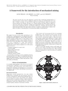
3 In addition,simulation and modelling techniques that canassist with this design process are alsodescribed. Figure 1 provides an illustration ofthe generic process used to design a chemicalor metallurgical plant. The shaded activitiesrepresent those areas and applications wherecomputer aids have been developed and arereadily available and can provide significantbenefit to the design process . This generalapproach has been termed Computer-AidedProcess Engineering (CAPE) by the AmericanInstitute of Chemical Engineers. Computer aids can be applied in a similarmanner in the metallurgical industry tofacilitate the design process . However, it mustbe kept in mind that high quality experimentaldata will be required in order to make effectiveuse of simulation, particularly in the case ofthe leaching and CIP/CIL processes.
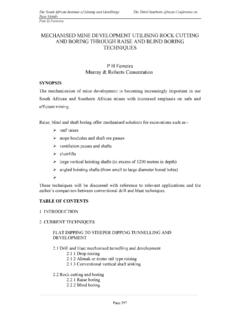
4 These dataallow the simulator to be calibrated for theparticular scenario that is to be examined andcould be obtained from the laboratory, pilotplant and/or full-scale plant. In the case ofleaching and CIP/CIL, such data are relativelyeasy to obtain for existing plants, assumingthat the problem is one of the design of anupgrade for an existing plant. In the case of anew plant, such data are much more difficultto come by, particularly if the ore is from adeep underground mine. In this case, the mostappropriate approach is to use experimentaldata obtained from a similar pulp on acurrently operating overview and descriptionThe CIP processA block-flow diagram of a typical CIP plant fora non-refractory gold ore is shown in Figure I and Table II illustrate the capital andoperating cost breakdowns for a typical SouthAfrican gold plant.
5 These figures are not astandard but reflect the nature of the ore andthe design basis for a particular ore is first reduced in size (typically80% passing 75 m) to ensure that all non-refractory gold is readily accessible for cyanideleaching. There are several variations ofcomminution circuits used in the goldindustry, such as: Multi-stage crushing and pebble and/orball milling circuits, typical of process design of gold leaching andcarbon-in- pulp circuitsby W. Stange**Hatch Africa (Pty) Ltd,, Woodlands Office Park,Woodlands, Johannesburg, South Africa. The South African Institute of Mining andMetallurgy, 1999. SA ISSN 0038 223 + Paper received Jul. 1998; revised paperreceived Aug.
6 process design of gold leaching and carbon -in- pulp circuits 14 JANUARY/FEBRUARY 1999 The Journal of The South African Institute of Mining and MetallurgyFigure 2 The carbon -In- pulp (CIP) processFigure 1 Computer-Aided process Engineering (Cape)DefineprocessobjectiveMostlymanual activityMostlyComputerizedActivityCollec tinformationAlternativeprocessroutesSynt hesizeflowsheetsSelect equipmentand conditionsSteady-StateprocesssimulationL aboratoryand pilotplant dataEquipmentsizingCostestimatesOptimiza tionSensitivityanalysisKeyProcessdoes notworkRegeneratedcarbonFreshcarbonGoldS teamEluantCyanidehydroxideHydrochloricac idLoadedcarbonCyanideair/oxygenLimeflocc ulantRun of mineoreProcessworksProjectfeasibleProjec tInfeasibleRejectDynamic and controlsimulationSafety andoperabilityanalysisDetailed plantdesignConstructioncommissioningoper ationsLeachingThickeningCrushing
7 And/ormillingResiduedisposalCarbonadsorp tionCarbonconditioningElectrowinning/zin c Single-stage semi-autogenous (SAG) or autogenous(AG) circuits and primary single stage SAG circuitsfollowed by secondary ball comminution the pulp is normally dilute andthickening (6-12% solids by mass) is performed to increasethe pulp density to about 50% solids by mass. This reducesthe size of the leaching plant that would be required as wellas reduces the amount of leaching reagents required. Manygold plants use conventional thickening with flocculantaddition. High rate thickeners, as well as de-wateringsystems that use cyclones only or cyclones and high-ratethickeners can also be used in reagents in the form of cyanide and an oxidantsuch as air or oxygen are added after thickening.
8 Leachingtakes place in a series of agitated leach reactors or leaching the pH of the pulp is normally adjusted to avalue of around 11 to ensure minimum loss of cyanideas hydrogen leaching of gold can be conveniently represented bythe Elsener equation:[1]Although air agitated leach tanks were commonly used inthe industry, mechanically agitated reactors are preferred dueto lower operating costs. Typical residence times in the leachsection may range from 20 40 hours depending on the head-grade and nature of the ore and the number of leach reactorsin series may range from 6 to 12. After leaching , the pulp is passed over a feed screen toensure removal of tramp material such as wood-chips,plastics and grit larger than about mm.
9 This is done tominimize screen blocking in the adsorption section. Afterfeed pre-screening the pulp flows through a cascade of well-mixed adsorption tanks, typically 6 to 8 in practice is to have a mean pulp residence timeof about an hour in each tank. The tanks are normallymechanically agitated and each will contain a batch of carbonof concentration 10 25 grams of carbon per litre of pulp ( by volume carbon ). The carbon is retained in eachreactor by means of screens having an aperture of which allows pulp to flow through and out of the reactorwhilst retaining the carbon in the reactor. The gold aurocyanide complex in the aqueous phase isreadily adsorbed onto the activated carbon .
10 By the time thepulp leaves the last tank in the adsorption cascade theconcentration of gold in the aqueous phase is typicallybetween and ppm with a value of regarded as a practically achievable value for most well-designed and operated plants. This represents a gold recoveryof 90 99% depending on the tenor of the feed high recoveries are achieved because the carbon istransferred countercurrent to the main pulp flow. Transfer isnormally accomplished by pumping pulp and the associatedcarbon in a countercurrent direction. Due to the abrasivenature of the pulp a certain amount of degradation of carbontakes place within the adsorption section. carbon fines thatare produced by abrasion pass through the inter-stagescreens and move co-current with the pulp down theadsorption cascade.