Transcription of The SelecTion and TeSTing of ValVeS for lng …
1 The SelecTion and TeSTing of ValVeS for lng applicaTionSThe SelecTion and TeSTing of ValVeS for lng applicaTionSconTenTS Scope IntroductIon cryogenIc ValVe deSIgn for lng SerVIce eSd ValVeS ValVe TeSTing guIdance to InSpectorS when TeSTing ValVeS current codeS and StandardS applIcable to ValVeS for lng SerVIcenote: this document is designed to be a supplement guide to work in conjunction with the relevant codes and standards for cryogenic ValVeS and does not seek to usurp or override themScopethis document is intended to offer guidance to designers and operators on the general requirements for ValVeS for liquefied natural gas (lng) service. It is also considered to be applicable to ValVeS for liquefied ethylene and liquefied ethane service. the ValVeS in these services are generally designed with an operating temperature range of + 80 c to minus 196 c.
2 Some aspects may be applicable to ValVeS in refrigerated liquefied petroleum gas (lpg) service. this guidance is primarily intended for the shipping and storage of these products but may be applied throughout the lng and lpg industries as appropriate. nothing in this document seeks to override the applicable standards and codes that may be applicable to these the term lng is used in this document, it may be read as also being applicable to liquefied ethane and liquefied ethylene design requirements apply to ensure that a valve will work effectively in a cryogenic1 system. for example, the valve design must take into consideration thermal expansion and contraction and still provide a tight shut-off without leakage across the seat.
3 An aim in the casting design is for the material mass to be minimal to improve cool-down times, while still meeting the relevant design codes and standards. the potential problem of liquid lock in the valve body must also be document aims to introduce the fundamentals of cryogenic valve design and TeSTing in general and to consider the minimum technical requirements in more detail. the standards offered as examples are european committee for Standardisation, (cen), standards. however, the appropriate national codes or standards and class requirements should be referred to where applicable, or where they are more stringent. the major codes and standards on this subject are referenced in the used for lng service should always be designed to meet the relevant applicable cryogenic standard.
4 BS 6364:1984 is an example of such a national standard, that applies to all cryogenic ValVeS . Similarly, bS en 12567:2000 is an example of a current national standard for lng isolation ValVeS that covers the suitability and appropriate verification tests for lng service. another example of a national standard to consider is bS en 1626:1999 cryogenic vessels ValVeS for cryogenic service; this standard covers materials, design and of ValVeS for cryogenic Systemsthe basic engineering design criteria that apply to the decisions on where to place ValVeS and their function in cryogenic Systems include the need for isolation, flow control (throttling) and sampling. the major differences between ValVeS used for low temperature duty, compared with those in ambient temperature systems, arise from the nature of cryogenic fluids themselves and the special hazards of handling example, in the late 1950s a major fire was caused on an lpg plant when a single drain valve was left in what the operators thought was the closed condition.
5 In fact the valve had been shut on a plug of frozen hydrocarbon hydrate or ice, and when the ice/hydrate melted there was a major leakage of liquid product that led to a serious incident and 1 the term cryogenic refers to the branches of physics and engineering that study very low temperatures. as a strict definition of upper temperature limit for cryogenic systems is not presently universally agreed, for the purposes of this document, cryogenic is assumed to refer to service temperatures below minus 80 fatalities. Since then, codes of practice (ref 1) have recommended that, in situations where this type of incident could occur, two ValVeS are fitted in series and provided with a plugged outlet.
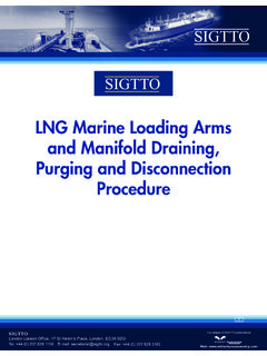
6 Liquid lock in the valve body is a feature where, by the action of closing the valve, some liquid becomes trapped in a cavity within the valve body. this is potentially dangerous because liquefied refrigerated gases, thus trapped, may exert sufficient pressure on expansion to cause plastic deformation of components, or ultimately rupture. this phenomenon is most significant in lng systems, although ValVeS in refrigerated lpg service may also be at risk. In practical valve design, any liquid trapped in the body cavity of a valve must have a relief path to prevent with internal relief to overcome this liquid lock phenomenon are usually marked on the body with an upstream and downstream label, or an arrow cast into the body.
7 It is essential to make sure the ValVeS are fitted the right way round. however, manifold ValVeS (which are bi-directional) should, if they are marked with a single arrow, have that arrow pointing outboard, or have the downstream side outboard. however, the presence of such indication does not, of itself, guarantee a satisfactory valve ordering replacement seats for cryogenic ValVeS it is important to specify the duty intended (eg operating temperature range or list of cargoes to be handled) because makers may use different materials for lpg, ethylene and lng duty in ValVeS that are externally identical. example of a pressure relief deviceone other important consideration during the design stage is the decision whether to fit flanged or welded ValVeS .
8 Experience shows that cryogenic systems may have some transient leakage from flanges when cooling down, especially large diameter systems, and in many cases designers seek to minimise this potential leak risk by fitting all welded ValVeS . an important practical consideration here is whether future maintenance, such as seat replacement, can be carried out with the valve in position. It is also important to consider if the total line length between flanges still allows for future repair and design considerations that are of specific relevance to cryogenic systems are the possibility of plugging due to ice or hydrate formation (in practical terms, usually only encountered with lpg) and brittle fracture of materials unsuitable for cryogenic applications .
9 The incident outlined, where lpg flowed out of a drain system when the hydrate melted, is one example of such an occurrence. Similar concerns may arise from the inadvertent opening of a drain valve as that could cause cryogenic liquid to spray unexpectedly onto a steel structure and result in brittle fracture . as an example, a quarter-turn ball valve used for sampling on a cargo pump discharge line on an lng carrier would usually have a plugged or blank-flanged outlet. however, if the blank was left off, for example, after atmosphere TeSTing during gassing up , and the ball valve was knocked accidentally during a subsequent cargo discharge as someone passed by, maybe during night hours, the stream of lng could cause the deck steel to fracture before it could be stopped.
10 It is to be expected that a cloud of flammable vapour would also be formed. this is why duplicated needle-type ValVeS (as the multi-turn operation helps to avoid this scenario) are to be preferred, particularly for sampling ValVeS , and with sufficient distance between them to minimise the hydrate blockage risk. (ref. 2) Systems used for vapour only pose less risk and so may have single sample ValVeS with blanked or plugged feature of cryogenic ValVeS is the extended bonnet & shaft design. there is no hard and fast temperature threshold for when such arrangement is used, but most designers adopt this layout for cargoes below minus 55 c. therefore, ValVeS with extended spindles and bonnets are normally used in ethane, ethylene and lng service, and are less usual for refrigerated lpg applications .