Transcription of THE SERIES TRANSAXLE GEARBOX UNITS - Hewland Classic
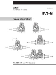
1 THE SERIESTRANSAXLE GEARBOX UNITST hese UNITS are designed for use with 300 to 450cu. inch competition engines, and are manufac-tured as two, four and five speed models. Thepresent manual deals with the four speed unit (LG 500) and the five-speed unit (LG 600).Only one final drive ratio is used ( : 1). Sincethe drive is indirect at all times, any change inratio can be made through the GEARBOX . The driveis taken from the clutch shaft to the hypoid finaldrive via straight cut gears. Gear change is effec-ted by non-synchronised face dogs. Ratios canbe changed without removing the unit from thechassis, and all requirements can be met fromOUT extensive range of gears.
2 All ratios exceptbottom are inter-changeable, and may be arrangedin any differential and crown wheel assembly ismounted on two taper roller bearings, located inthe side plates and adjustable to correct load by shims. Output shafts are also mounted inthe side plates, and lip oil seals are fitted. Thepinion is supported by a double angular contactbearing clamped to the case directly behind thegears. This bearing accepts the major radial andthrust loads, while a roller bearing supports thetail. Thus pinion mesh can never be affected bycase gears run directly on caged needle rollerbearings, and each gear and bearing revolves asan assembly.
3 Heat treated nickle-chrome steelis used for all gears and shafts. Selector forksare cast in aluminium bronze, and casings inmagnesium differential is of Limited Slip design, andtwo types are manufactured. The unit normallysupplied the cam and type. The other isthe type, operated by flat clutchplates. Both UNITS are GEARBOX unit is lubricated by oil splash, andthe final drive by pump. The pump is located inthe main case, and is fed via a filter which canbe withdrawn from the of the case. Theoil is piped out of the main case on the hand side and returns via external piping, thusproviding for the fitting of an oil cooler.
4 Thelatter is strongly recommended to ensure thatoil temperature does not exceed its maximum of110 C (250 F).The gear-change rod is mounted high on theright-hand side of the unit to facilitate the instal-lation of the gear line linkage. The clutch operated by steel fork and push-rod acceptedas the simplest and most reliable system, especi-ally with monocoque chassis. The push-rod isactuated from a slave cylinder mounted on theside of the main general configuration of the LG SERIES pro-vides the maximum utilisation of power alliedto minimum weight for the power required to betransmitted. IndexBacklash, adjusting Bearing Carrier (Main).
5 Bearing Carrier (Clutch shaft)..Bearings and pinion, front and pinion, tail ..Clutch Rings ..Clutch Shaft ..Crown Wheel ..Crown Wheel Pinion, setting up ..Differential unit , removal..Differential unit , dismantling..End Ratios, Ratios, standard and ..PAGE14699, 1466912, 14149126126616 76, 7 PAGEMain Case and Diff. 9 Oil, and , 12 Oil Pump..Oil Filter Pinion ..Plungers..Pre-load, Idler GearSelector Finger10, , 1461496, 7 Selector Forks, Forks, setting , Selector , 7 Setting upCrown Wheel Plates, Plates, specification..23 General notes on maintenance and overhaulOnly genuine spares should be used as re-placements. These are manufactured in our own work-shops to the fine tolerances necessary, and rigorouslyinspected and nuts and gaskets should always be used on warming the outside of the case, keep the lamp moving.
6 Do not overheat. Test with a spot ofmoisture, which will bounce off when the case is refilling with oil, put half the quantity into eachfiller hole. Never put all the oil one oil List NUMBER Nyloc NutsStud Bearing Corrier___ SteelBall Selector RodSpring Selector Rod ScrewPlungersStud StudWasher 6 Blanking PlugSelector Finger HousingPIungerSpringPlug BushAlloy SpacerScrew..End CoverEND Cover Rear StartOil Seal End CoverCover Starter SplineAllen Cap ScrewsNyloc Nut UNF Filler CapSleeve Oil SealStarter Sleeve Hub First Second Reverse Tail F T 2013LG 2025LG 5 202F T 2021 FT F T 2027F T 2028203HC F T 2032F T 2035F T 2036L G 20310F T 20311LG 204LG 204 RLG2041LG4 2042LG4 2043LG4 2046L G 2044LG 2045L G 20416L G 20417 LGS 226LG2261LG 227L G 228L G 2291L G 2292LG4381214312111144111443862214314111 REMARKS5 SpeedNot IllustratedNot I I lustratedNot IllustratedNot IllustratedNat IllustratedNot IllustratedNot Not IllustratedNot lllustmted5 Speed4 NUMBERT hrust WasherPinion NutWasherSplit PinReverse First Sliding GearClutch Ring 5 SpeedBearing
7 FrontCirclip RearThrust Washer Swcer LovshaftSelector Rod First Reverse NutSelector Selector Rod Selector Fork LG5 234 RsLG4 234 Rs 2341LG 2342LG 2343LG 2345LG 2346LG5 246FT 2462LG 247LG5 249 Selector Fork LG5 250 Selector Fork Adjusting SpacerSelector FingerGasket End CoverGasket Selector Finger HousingPinion Gears All RatiosLayshoft Gear LG5 251--- LG 252LG 260LG 261 Loyshaft Gears Other Ratios LG 2295LG 230LG 2301LG 2302 231LG 232 LG5 234! Speed4 Speed5 Speed4 SpeedRear Start 5 SpeedRear Start 4 Speed5 Speed4 Speed5 Speed-4 Speed5 Speed4 SpeedMode on Assemble5 Speed 17 I 15 GEARBOX unit , SPARES LIST AND DIAGRAM5 The GEARBOX REMOVING THE UNITEND the nuts and washersfrom te end cover.
8 Take off cover and the split pins from the castellatedpinion and the heads of the two outside selector rods,thus engaging the the pinion nut and washer and slackenoff the withdraw the two outside selector rods, todisengage the CARRIER1. Remove the UNF nuts and washers,and the UNC cap Using a plastic mallet, tap the bearing carrierand remove it from the main case, withlay-shaft assembly and gear train. Support thegears, hubs and clutch rings with the hand, asthey come off the in reverse order to RATIOSWhen changing a gear ratio, take off the slackenednut and remove the from the bearing are exchanged in pairs one from the shaft and one from the pinion shaft.
9 Each gear isetched with two numbers. The first is the number ofits own teeth. The second is the number of teeth onits mating is essential that gears be correctly pairedaccording to these THE GEAR hubs, clutch rings and gears. Wash andinspect for wear and cracks, giving particularattention to the clutch forks for heavy or uneven wear, andtest for excessive play between forks and forks are not to be stripped, check that nutsare tight and properly tabbed. To continueKnock back the tab and unscrew the nut from the fork, (44). Remove the bung, spring and plunger (13, 14, 15)from the selector finger or by sliding it into the selector head, and pushing the rod the head is clear of the others.
10 (On the 4-speed GEARBOX , to remove selectorfinger it is necessary to undo reverse selectorfork and push rod down until head is clear ofthe others).Take off the Selector Finger Housing by undoingthe cap screw and two UNF nuts. Thenremove the two remaining the three cap screws (6) and take outthe top Selector Rod Springs and balls. Thentake out the three Selector Rods, followed bythe bottom balls and the UNC cap screw (11) -and pushout the locking pinion tail bearings andrenew if necessary. To remove, warm up surround-ing in reverse order to above, subject tothe replacing bottom balls and springs, set upto correct one-third of the ballshould be exposed.