Transcription of “The Survivor” A 80 meter QRP SSB transceiver
1 The Survivor A 80 meter qrp ssb transceiver ~10 watts pep @ uV receiver sensitivity Up to 350 kHz tuning range 8 ohm 500 mw speaker output. Tune and CW modes 50 ma Rx current (with optional Digital Dial) small size 6 x 4 x , at 2A min recommended power supplyOperation:Controls: Controls consist of Volume, Fine and Main (course) tuning. Volume: Set the volume control to a comfortable listening level. The AGC will hold the audio level to this volume for all but the weakest signals. The AGC has a slightly delayed response to keep it from overshooting when a large signal appears. This results in a momentary thump . Without the slight delay, all audio would be lost until the AGC could recover from overshooting, which could take several seconds.
2 Main tuning:Main tuning has about a 350 kHz range in a single turn of the knob. This much range is a bit touchy to tune in a signal, so main tuning is augmented by a fine tuning control. NOTE: Tuning is backwards . Turning the tuning knob clockwise decreases frequency. Fine tuning: The fine tuning control has about a 30 kHz range, allowing you to tune between several near-by stations and to compensate for any minor drift the VFO has during operation. Microphone: An electret microphone element is required. The rig supplies the power needed for the mic. A suitable, low cost microphone is available from Push To Talk (PTT): Transmitting is initiated by pushing the PTT button on the microphone and then talking (duh). The PTT switch is also used to activate tune and CW modes.
3 Tune up mode:Most 80 meter antennas have a fairly narrow bandwidth so therefore require an antenna tuner which needs to be readjusted every so often as you move up or down the band. Since a steady carrier works better then whistling into the mike to get a signal, a steady carrier or tune mode is built into the rig. Tune mode is activated by: very short push and release of the PTT switch on the microphone, < 1/2 second. beep will sound in the audio output, announcing the tune mode is now active. the PTT will now activate a 600 Hz tone which is injected into the microphone circuit to modulate the rig. The tone is also heard in the speaker when the rig is transmitting. Transmit power is typically about 5 watts in tune mode, but will vary depending on the microphone gain setting.
4 Exit Tune mode, perform another very short push and release the PTT switch. double beep will sound in the audio output to announce the tune mode is no longer active. CW [Morse] mode:The Survivalist can be operated in CW mode thanks to the Tune mode and microprocessor control of the T/R sequencing in the transceiver . The difference between CW and Tune mode is that in CW mode, the transceiver must respond to quick changes in the state of the PTT switch and stay in the CW mode. Once enabled, CW mode can only be cleared by turning the rig off, then back on again. CW mode is enabled by keying the character H with the PTT at between 5 and 20 wpm. This allows activating CW mode with either a straight key or external paddle. There will be no annunciating side tone until CW mode is enabled, so you have to mentally count the key taps to enter the mode.
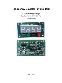
5 If not enough pulses are detected, the rig may enter Tune mode instead of CW mode. There just has to be four on/off pulses detected in less than second to enter CW mode. When CW mode is detected and enabled, the audio output will annunciate CW . The Survivalist will now operate as a CW transceiver , allowing for cross mode communication in the phone band. 1 Parts placement diagram, color coded. Mostly completed board. The picture illustrates how a well constructed board should look like. 2 Picture 1, mostly assembled boardParts list: ohmsGRN/BLU/GLD/GLDAll resistors are 1/4w, 5% CARBON FILM210 ohmsBRN/BLK/BLK/GLD151 ohmsGRN/BRN/BLK/GLDthis value is easy to mix up with 1 Meg same colors, reverse order. 6100 ohmsBRN/BLK/BRN/GLD3220 ohmsRED/RED/BRN/GLD121 KBRN/BLK/RED/GLD610 KBRN/BLK/ORG/GLD322 KRED/RED/ORG/GLD247 KYEL/VOL/ORG/GLD13100 KBRN/BLK/YEL/GLD11 MEGBRN/BLK/GRN/GLD22 K trimmer6mm 110 KPanel mount with switch150 K or 100 K Panel mount control, 12 uHyGRY/RED/GLD/GLD - RFC1120 mHy124 Larger black cylinder IF cans1 Poly-variable Tuning cap170 pfd Brown trimmer cap1139 pfd39 NPO disk5150 pfd151 C0G MLCC3330 pfd331 disk or MLCC 5680 pfd 100V681 C0G uFd102 disk11200 pfd 100V122 mono 100V uFd104 X7R 50V uFd 100V 104 FILM.
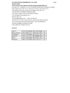
6 BOX51 ufd / 50 VALUM ufd /50 VAlum electrolytic347 uFd/16 VAlum electrolytic1330 ufd/16 VAlum electrolytic1 RED LED T1 2J-176P-channel j-fet TO-9212N3906 PNP TO-9222N3819N-channel j-fet TO-9282N3904 NPN TO-9242N7000 MOSFET TO-921 FQN1N50 CTA500V MOSFET TO-921 IRF510 PBFP ower mosfet TO-220178L055V, 100 ma regulator21N4148SS zener311N4756B47 V 1W zener11N58171A shottky diode2SA612A8 pin DIP mixer/osc1LM358N8 pin DIP dual op amp2LM386N8 pin DIP Audio amp174HC4053N16 pin DIP multiplexer1 ATTINY13A8 pin DIP Atmel processor68 pin DIP socket116 pin DIP MHz, series HU-49US crystal matched1FT50-42 Black, Ferrite core, large1FT37-42 Black, ferrite core, small2T50-2 Red powered iron core1T50-7 White powered iron mm Power Jack, PC mount2 Stereo panel jack1 BNC panel jack1TO-220 insulatorMica 1#4, 1/2 Nylon screw1#4 nut for above1 Main PCB1 Case, top1 Case, bottom1 Red film2 Small knob1 Large knob1 Tilt stand bale2 Bale mounting blocks4 Rubber feet7# 4-40 1/4 pan headscrews2# 4-40 1/4 flat headscrews15 feetInsulated hook up wire, #2415 feet#24 magnet wire12 feet#28 magnet wire4 Print this large, ink jet printer friendly parts placement and value diagram for easy reference during assembly.
7 Experienced builders will likely only need this diagram to stuff most of the board, but review the assembly instructions for any notes. 5 Assembly tips: Presort the various parts and place similar types in small paper picnic bowls. Resistors in one, capacitors in another, and so on. This will not only speed assembly, but will also help keep parts from getting lost. If you like, you can also cross check the parts against the parts list as you do this to make sure you have them all. Be sure to print out the black and white parts placement diagram as this will be easier to reference most of the time. You really don't have to print out the whole manual if you have a laptop or equivalent on your workbench to view this. Hopefully you already know how to solder and don't need to be told to heat both the component lead and the solder pad with the tip of the soldering iron.
8 Be stingy with the solder. You don't need much, only enough to fill up the hole. Using diameter solder allows better control then the more common . The circuit board is assembled in the order of parts height. Low profile parts starting with resistors are installed first, the progressively taller parts are added. Q16, the transmitter output transistor will be the very last part mounted and only after the board has been wired into the case and tested. If you bought the Digital Dial option, it would be a good idea to built and calibrate this first. The Digital Dial can be used to adjust the VFO coil to put the tuning into the proper range. Cabinet prep: There is a Modulation indicator LED on the board, which you might want to bring out to the front panel.
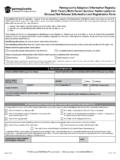
9 This would require drilling a small hole someplace on the front, which would best be done now. If desired, paint the cabinet. Tape the red film over the display cutout on the front panel. If you'll be using the optional Digital Dial, snip the corner of the film to uncover the switch hole. Attach the tilt bail to the bottom of the case and add the four rubber feet bumpers. Attach the decals as described below. The decals are applied the same as model decals. Cut around each group of text or symbols you wish to apply. It doesn t have to be perfect as the background film is transparent. Apply the decals before you mount anything to the chassis. Use the above picture to get the correct spacing around the holes and cutouts, as it is very easy to do a great decal installation and have a portion covered up with a knobThoroughly clean the surface of the panel to remove any oils or contamination.
10 We have found that moving the decals into position on bare aluminum chassis is difficult, due to the brushed surface, so we advise pre-coating the chassis with the Krylon clear before applying the decals, and then, after as around the decal. After trimming, place the decal in a bowl of lukewarm water, with a small drop of dish soap to reduce the surface tension, for 10-15 seconds. Using tweezers, handle carefully to avoid tearing. Start to slide the decal off to the side of the backing paper, and place the unsupported edge of the decal close to the final location. Hold the edge of the decal against the panel, with your finger, and slide the paper out from under the decal. You can slide the decal around to the right position, as it will float slightly on the film of water.