Transcription of The Touareg Electrical System - VolksPage.Net
1 The TouaregElectrical SystemDesign and FunctionSelf-Study Programme off-road vehicle features a number of hi-tech convenience systems for improved Self-Study Programme is designed to help you learn about the Electrical and electronic systems in the Volkswagen h i c l e s w i t h off-road capability are no longer just utility vehicles for a limited group of all levels in the population they are now becoming more and more sought ImportantNoteThis Self-Study Programme explains the design and function of new contents will not be refer to the relevant Service Literature for current inspection, adjustment and repair.
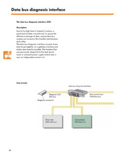
2 4 Onboard power supply .. 14 Battery concept .. 20 Power supply .. 28 Onboard power supply management.. 30 Lighting .. 38 Networked functions .. 42 Service .. 54 Glossary .. 56Te st yo u r se l f .. 584 Fitting locationsThe fuse boxes and relay slots can be found at various locations in the vehicle due to the fact that the onboard power supply does not have a central illustrations here provide an overview of their fitting boxon right under dash panel E-boxon left under dash panelE-boxon left in plenum chamber More detailed information can be found in the electronic service information System (ELSA).Fuse boxes and relay slots in vehicle's Electrical system5 Fuse boxon left of dash panel Back-up fuse boxunder driver's seatS298_001 Onboard power supply batteryunder driver's seatStarter batteryunder luggage compartment6 NetworkingIn order that the control units can exchange information between each other, they are connected in a network via the Gateway in the dash panel insert data exchange allows the control units to access various kinds of information in the vehicle.
3 The more information a control unit has about the current driving situation, the greater the level of safety and e n s u r e t he exchange of data can take place, the control units are connected together in a network via a CAN bus System . Due to reasons of safety and because the data bus systems work at different rates of transfer, the control units are allocated to different CAN bus systems. If one data bus System should fail, the others can continue to function. The CAN bus systems are separated as follows-Drive Train CAN bus,-Convenience CAN bus,-Infotainment CAN Train CAN busConvenience CAN busInfotainment CAN busCAN busCommunications lineVirtual Communications lineS298_027J623 Engine control unitJ234 Airbag control unitJ401 Navigation control unitJ526 Te l e p h o n e c ontrol unitR128-channel amplifierR78 TV tunerJ499Te l e m a t i c s control unit (USA only)J162 Additional water heater control unitJ400 Wiper motor control unit* Turbocharger control unitJ285 Dash panel insert (Gateway)*ReservedThe data bus network7S298_003J217 Autom.
4 Gearbox control unitJ104 ABS with EDL control unitJ646 Tra n s fe r box control unitJ647 Tra n sve r s e lo ck - up control unit* Off-road stabilisation control unitJ197 Adaptive suspension control unitJ518 Entry and start authorisation control unitJ527 Steering column electronics control unitJ393 Convenience System central control unitE265 Rear operating and display unit for ClimatronicJ519 Onboard power supply control unitJ345 Tra i ler detection control unitJ446 Parking aid control unitJ386 Driver door control unitJ387 Front passenger door control unitJ521 Seat adjustment control unit Front passenger memoryJ388 Rear left door control unitJ389 Rear right door control unitJ343 Left gas discharge lamp control unitJ344 Right gas discharge lamp control unitJ255 Climatronic control unitJ502 Tyre pressure monitor control unitJ136 Seat adjustment control unit Driver memory*Reserved8 Control unitsThe illustrations here provide an overview of the fitting locations.
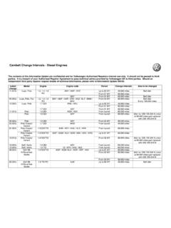
5 The Drive Train CAN bus operates at a data transfer rate of 500 kbit/s. The data is transmitted via the CAN High and CAN Low line. Both wires are entwined together. The cable colour for CAN High is orange/black and for CAN Low it is Engine control unit J623in right of plenum chamberABS with EDL control unit J104 in right of plenum chamberSteering column electronics control unit J527on steering columnAutom. gearbox control unit J217 Transfer box control unit J646under front passenger's seatThe control units in the Drive Train CAN bus9 Airbag control unit J234under centre console coverEntry and start authorisation control unit J518on left under dash panelWindscreen heater control unit J505under driver's seatControl unit is not connected to CAN busS298_002 Adaptive suspension control unit J197on right in luggage compartmentTra n sve rs e lock-up control unit J647on left at rear in wheel housing10 Control unitsThe illustrations here provide an overview of the fitting locations.
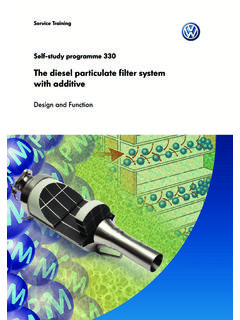
6 The Convenience CAN bus operates at a data transfer rate of 100 kbit/s. The data is transmitted via the CAN High and CAN Low line. Both wires are entwined together. The cable colour for CAN High is orange/green and for CAN Low it is orange/brown. The CAN bus is single wire compatible, which means that if one CAN bus wire should fail, the CAN messages can be transmitted via the other wire. Introduction Climatronic control unit J255in left of dash panelSteering column electronics control unit J527on steering columnEntry andstart authorisation control unit J518 Onboard power supply control unit J519on left under dash panelThe Drive Train CAN bus control units11S298_044 Parking aid control unit J446on left at rear in wheel housingRear left door control unit J388 Rear right door control unit J389behind door trim Convenience System central control unit J393 Tra i le r detection control unit J345on right in luggage compartmentDriver door control unit J386 Front passenger door control unit J387behind door trim on left and rightTyre
7 Pressure monitor control unit J502on left A-pillar12 Control unitsThe illustrations here show the fitting locations of the control units for the Infotainment CAN bus. The Infotainment CAN bus operates at a data transfer rate of 100 kbit/s. The data is transmitted via the CAN High and CAN Low line. Both wires are entwined together. The cable colour for CAN High is orange/violet and for CAN Low it is orange/brown. The Infotainment CAN bus is single-wire compatible, which means that if one wire fails, data can be sent and received via the other Wiper motor control unit J400in plenum chamber Te l e p h o n e c o n trol unit J526under front passenger's seatThe Infotainment CAN bus control units13 Amplifier R12CD player R41 (not connected to CAN bus)TV tuner R78on right in luggage compartmentRadio RNavigation control unit J401in centre of dash panelAdditional water heater J162on left in wheel archS298_04514 The fuse boxes can be found in the dash panel on the left and right-hand side.
8 The back-up fuse box is under the driver's seat and the E-boxes can be found on the left in the plenum chamber and under the dash box on left of dash panelThe fuse box on the left of the dash panel, for example, houses the fuses for the following control units:-Onboard power supply control unit-Entry and start authorisation control unit-Tyre pressure monitor control unit-Engine control unit-Airbag control unit-ABS with EDL control unit-Steering column electronics control unit-Convenience System central control unit-and fuses for other Electrical consumers Onboard power supplyS298_004 Fuse box on left of dash panelThe fuse and Electrical boxes15 Fuse box on right of dash panelThe fuse box on the right of the dash panel houses the following fuses.
9 -Trailer detection control unit-Parking aid control unit-Telephone control unit-ABS with EDL control unit-Navigation control unit-CD changer-TV tuner-Radio-Radio amplifier-Convenience System central control unit -Adaptive suspension control unit-Automatic gearbox control unit-Convenience System central control unit-Telephone-and fuses for other Electrical consumersThe exact fuse allocation can be found in the electronic service information System (ELSA).S298_005 Fuse box on right of dash panel16 Back-up fuse box under driver's seatBack-up fuse box under driver's seatThe following fuses and relays can be found in the back-up fuse box:Fuses:-Fuse sockets -Fuse for terminal 15 relay-Battery parallel circuit relay-E-socket-Fuse for onboard power supply control unit-Starter lead diagnosis-Fuse for adaptive suspension , compressorRelays:-Battery master / isolation relay E74-Relay for terminal 15-Charging circuit relay for vehicles with dual battery Electrical systemE-box under dash panelThe following relays can be found in the E-box.
10 -Servotronic relay D1-Relay for tailgate closing aid D2-Relay for adaptive suspension compressor D3-Relay for power supply terminal 15 D5-Relay for additional water heater D6-Relay for heated rear windscreen D7-Relay for seat heating D8-Additional relay for brake lights D9-Relay for spare wheel E2-Relay for manual air-conditioning System E3-Relay for circulation pump E4-Relay for start-up consumers E5-Relay for headlight washer System E7-Relay for residual warmth E8 Onboard power supplyS298_006S298_007 Battery master / isolation switchRelay for terminal 15 Charging circuit relay for additional batteryE-box under dash panelD3D2D1D6D5D7D8D9E4E7E5E8E2E317E-box on left of plenum chamber The allocation of the fuses and relays is dependent on the engine type.