Transcription of The Transimpedance Amplifier - University of California ...
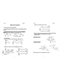
1 10 Winter 2019 IEEE SOLID-STATE CIRCUITS MAGAZINE A CirCuit for All SeASonSBehzad RazaviMMany of today s communication sys-tems incorporate a Transimpedance Amplifier (TIA). Although the TIA concept is as old as feedback ampli-fiers [1] , it was in the late 1960s and early 1970s that TIAs found wide-spread usage in optical coupling and optical communication receivers. In a patent filed in 1967, Miller proposes the circuit shown in Figure 1 [2] , which consists of two TIAs for converting a photodiode s current to a differ-ential output voltage. Additionally, these amplifiers have become popu-lar in radio-frequency (RF) receivers in the past 10 years [3]. This article deals with TIA design for optical and RF IdeaA TIA employs negative feedback to create a low input impedance. For example, a resistor RF placed around an Amplifier having an open-loop gain of A0- yields an input resistance equal to /()RRA1 Fin0=+ [Figure 2(a)].
2 As such, the circuit is suited to sensing a current, thus acting as a current-to-voltage converter. We define the tran-simpedance gain as RIVT inout= (1) IIRA0ininin=- (2) .AAR1F00=-+ (3)If ,A10& we have . course, a single grounded resis-tor can perform the same function [Figure 2(b)] and provide the same tran-simpedance gain. However, the principal difference is that Iin sees a low impedance in Figure 2(a) and a high impedance in Figure 2(b). The virtual ground introduced by the TIA proves useful in two cases: 1) If Iin incurs a large parasitic ca-pacitance, ,Cp to ground, in which case the pole at the TIA input is given by [/()]RCA1Fp01+- and that in Figure 2(b) by ;RCFp1-^h , the former potentially achieves a greater bandwidth.
3 2) If Iin suffers from nonlinearity for large voltage swings across it, the TIA reduces these swings by a factor of .A10+We describe in the following how these properties are exploited in re -ceiver Design for Optical CommunicationsAn optical receiver incorporates a photodiode to convert to current the information carried by modulated Digital Object Identifier of publication: 6 February 2019 The Transimpedance AmplifierPD3C2C4C3R2R152 RFRFA1A281046642 FIGURE 1: The TIA proposed by Miller. PD: + (b)(a)FIGURE 2: (a) The basic TIA structure and (b) use of a resistor to convert current to voltage. IEEE SOLID-STATE CIRCUITS MAGAZINE Winter 2019 11light.
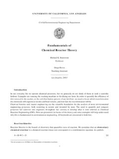
4 The diode suffers from a direct tradeoff between its output current and parasitic capacitance (because the light received by the diode is propor-tional to its area), necessitating a vir-tual-ground termination [Figure 3(a)]. Optical receiver TIAs must achieve a wide bandwidth, a low input-referred noise current, and a reasonable gain to minimize the noise contribution of the subsequent simple, the topology of Figure 3(a) faces several challenges. As a rule of thumb, we select the cir-cuit s bandwidth equal to 70% of the data rate, , equal to 28 GHz for a 40-Gb/s system (which implies the open-loop bandwidth must be quite large). This choice minimizes inter-symbol interference but must deal with the noise integrated across such a large bandwidth. For these rea-sons, the core Amplifier , ,A0 typically includes only one gain stage and one main noise in Figure 3(b) is an exam-ple consisting of a common-source (CS) Amplifier and a source follower.
5 The CS stage can employ induc-tive peaking to increase the band-width. Assuming a voltage gain of about unity for the follower, we approximate the open-loop gain by ,AgRmD01= obtaining RgRgRR1 TmDmDF11=+- (4)at low frequencies. The output volt-age is available at V1out and at ,V2out with the former exhibiting a more design-friendly dc level but also a higher output determine the input-referred noise current, we leave the input port open; model the noise of ,,,MRMD12 and I2 by a voltage quantity V,n2core at the gate of ;M1 and note that RF also contributes noise [Figure 3(c)]. Calculating V,n2out and dividing it by ,RT2 we have IRVV,,,nFnnRF2222incore=+ (5) .RVRkT,FnF22core=+ (6)If we target, , /I10pAHz,nin= and choose ,R1kFX= then V,ncore must not exceed nV/.
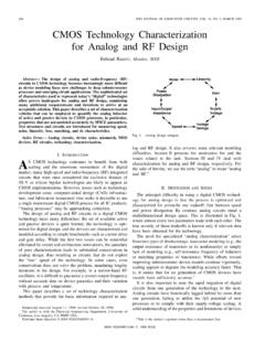
6 Hz We prefer that only M1 be the main noise contrib-utor. In practice, however, the limited voltage drop across RD makes this resistor s contribution significant as TIA topology of Figure 3(b) must satisfy the bias condition ,VVIRVGSGSDDDD121++= a difficult issue at low supply voltages. Let us then omit the source follower [Fig-ure 4(a)], recognizing that the volt-age headroom equation reduces to .VIRVGSDDDD11+= That is, this cir-cuit can incorporate a greater RD and achieve a higher open-loop gain. It can be shown that the input resis-tance rises to ,RgRRR1mDDF1in=++ (7)and the Transimpedance gain is given by ().RgRRgR11 TmDDmF11=+- (8)To further ameliorate the voltage head-room problem, we can inject a constant current, ,Ib into RF to create a volt-age drop of, say, 300 mV [Figure 4(b)], obtaining VIRIRVGSbFDDDD11-+=.
7 As a result, RD can sustain a greater voltage drop and yield a higher open-loop alternative TIA topology em -ploys a CMOS inverter as the core L1ID1 Vout1 Vout2 VDDD1 XRDRFP hotodiodeD1cpX +A0 RFVoutM1M2I2 RFVn,RF2Vn,out2Vn,core2++ +A0(b)(c)(a)FIGURE 3: (a) A TIA receiving current from a photodiode, (b) circuit implementation, and (c) TIA noise (a)(b)FIGURE 4: (a) A TIA using a common-source stage with feedback and (b) use of a constant current source to shift the output dc level Winter 2019 IEEE SOLID-STATE CIRCUITS MAGAZINE Amplifier [4] . Depicted in Figure 5, this structure eliminates the noise due to RD in Figure 4(a). The input resistance and gain can be found from (7) and (8), respectively, if RD"3 and gm1 is replaced with ,ggmm12+ Rgg1mm12in.+ (9) .RggR1mmTF12.
8 +- (10)This topology exhibits a lower input-referred noise current but a higher input receiver TIAs often uti-lize series inductive peaking to in -crease the input bandwidth. As shown in Figure 6, an on-chip in -ductor, ,Lin creates a second-order network at the input, yielding a band-width of ,RCA21dBFp30.~+-^h (11)if the damping factor is chosen equal to /.22 TIA Design for RF ReceiversA common situation in RF design is that the receiver senses a weak desired signal along with a strong interferer (blocker). Upon traveling through the receive chain, the blocker is ampli-fied and can introduce substantial distortion. The chain must therefore be designed for sufficient linearity up to the stage(s) where the blocker is filtered. In general, as the volt-age swing at each interface is minimized, the linearity improves.
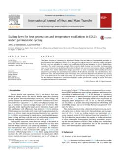
9 We then contem-plate the use of current-mode signals and low impedance levels to reduce the volt-age 7(a) illustrates a typical modern RF receiver front end [3]. The signal and blocker combinat ion sensed by the antenna drives a Gm stage (a voltage-to-current converter), and the resulting current Iout is applied to a passive mixer to generate a baseband current .IBB The low impedance established by the TIA at Q and P reduces the voltage swings at these nodes, thus improving the lin-earity of the Gm stage and the mixer switches. This means that the large blocker can be tolerated at least up to node .QThe TIA in Figure 7(a) must still meet stringent noise, linearity, and gain requirements. The input-referred noise current, given by (6) and di -vided by ,Gm2 must be sufficiently smaller than the input-referred noise voltage of the Gm stage.
10 The TIA must also handle large voltage swings at its output with negligible nonlinear-ity. Moreover, the TIA must provide enough gain to overcome the noise of the subsequent stages. The large blocker level still poses two trad-eoffs in TIA design, , one between the core Amplifier s bandwidth and the linearity at point Q and another between the closed-loop gain and the output voltage us consider the first tradeoff, recognizing that amp -lifier A0 in Figure 7(a) generates VBB such that /,VRIBBFBB. and hence VQ remains close to zero. In other words, if IBB varies fast and ,Q is to act as a virtual ground, then VBB must track .IBB This means that the ampli-fier must have a sufficiently wide bandwidth. Now, we note that the center frequencies of the desired channel and the blocker are translated by the mixer to zero and ,ff10- respectively [Figure 7(b)].