Transcription of The VHF / UHF « Eggbeater » Antenna ~ Revisited
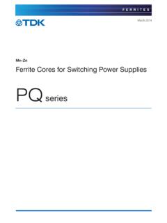
1 The VHF / UHF E ggbeater Antenna ~ Revisited ~ ON6WG / F5 VIFA new simple way to build the Eggbeater Antenna IntroductionPrevious designs described in VHF / UHF Eggbeater Antenna ~ Part 1 and VHF / UHF Eggbeater Antenna ~ Part 1 Appendix A have used an unbalanced coaxial line, or a balanced line, a BALUN transformer and a phasing line section to provide a good match to 50 ohms. The fact is that the design described in Part 1 ( still widely used because of it's simplicity) is not a proper way to connect the feed line to the Antenna and the design described in the Appendix A section is a little bit tricky to document introduces a new simpler way to build the Eggbeater Antenna .
2 It introduces also a technically proper way to construct the Eggbeater Antenna in order to achieve the best designSome parts of the concept have been described in the Appendix A section. Therefore for more details please refer to Appendix A section. However the main lines are reminded avoid imbalance in the Antenna system, the Antenna requires a feed line carrying equal and opposite currents between the two loops. Only a parallel two conductor feed line will give this result. This type of system called phasing line is simple to build. So it will be used in this design. The detailed schematic of such a system is presented below in Fig A. Page 1 Note about the schematics presented belowFor clarity, Fig A and Fig B, presented below show the loops separated, but in reality they aremounted at right angles to each other and one loop is mounted inside the other loops are connected to each other with a line made of two parallel pieces of coaxial cable RG-58.
3 These two pieces of coaxial cable are one quarter wavelength. The braids are soldered together at both end. With this type of connection the impedance of the phasing line is 100 the loops are connected in parallel, the impedance at points C and D or A and B is 50 line calculation 1) Impedance : After calculation, the impedance of the phasing line section is 100 ohms. ( Phasing line section formula : Z0= (ZL x ZA) (200x50) 10000 = 100 ) Therefore the phasing line section can be constructed with 50 ohm coaxial cable RG-58 . 2) Length ( VHF Eggbeater ) : [(300 / F(in MHz) : 4] x coax. velocity factor [(300 / 145) : 4] x 0,66 => 34,15 cm [( / F(in MHz) : 2] x coax. velocity factor [( / 145) : 2] x => inches : velocity factor for coaxial cable RG-58 : is a usual value.
4 3) Length ( UHF Eggbeater ) : [(300 / F(in MHz) : 4] x coax. velocity factor [(300 / 435) : 4] x 0,66 => 11,38 cm [( / F(in MHz) : 2] x coax. velocity factor [( / 435) : 2] x => inchesWe are now in presence of a balanced load. To avoid current flow over the outside of the coaxial shield of the feeder, and consequently, distortion of the Antenna pattern, radiation loss, and elliptical polarization, this system requires a balanced feed for proper operation. Such balanced system comprising a BALUN and a Q-Section phasing line is described in the Appendix A section. Page 2 Nowadays, with the development of new technologies in the field of ferrite materials, replacing a BALUN made of coaxial cable by ferrite round cable cores (sleeves) has become will simplify greatly the design of the feeding achieve the proper feeding system, a 50 ohm coaxial cable is used.)
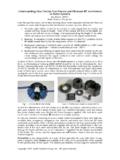
5 Then a choke BALUN is added by slipping ferrite round cable cores over the outside of the coaxial cable and place them as close as possible to the feed point. These ferrite sleeves will stop any cable radiation. The coaxial cable will be connected at points A and B or C and D . Such a system is shown below in Fig is beyond the scope of this article to explain how a choke BALUN made with ferrite cores is working. However, documentation on the subject can be found among the references listed at the end of this document. The development of the choke BALUN described here is based on the information found in these articles and in the technical information published by Fair-Rite Products Corp. This choke BALUN requires three ferrite cable RG58 coaxial cable to feed the Antenna Ferrite cable cores PN 2643540002 were selected for the VHF Antenna design, and ferrite cable cores PN 2661540002 were selected for the UHF Antenna design, both from Fair-Rite Products.
6 Using RG213 coaxial cable to feed the antennaFerrite cable cores PN 2643102002 can be used in the VHF Antenna design and one can use ferrite cable cores PN 2661102002 in the UHF Antenna design, both also from Fair-Rite Products. Page 3 Fig CFig C shows three ferrite cable cores PN 2661540002 slipped over a RG-58 coaxial cable. The ferrite cores are fastened close to the open end of the cable. Then the open end of the cable will be connected to the UHF handling The power that can be handled by the Antenna is limited by the use of ferrite sleeves. With the use of three ferrite sleeves the Antenna can handle easily 40 to 50 watts. If more power is needed the temperature of the ferrite cable cores must be verified. The temperature must stay at a low level.
7 If the temperature rises too much, one or more ferrite cable cores must be added. Adding ferrite cable cores will rise the choking impedance and consequently will reduce the common mode current. This common mode current must be reduced to such a level that the choke cannot be overheated and thus lose its properties, damage the ferrite cores or the coaxial cable. Practical test and resultsTests have been performed on a UHF Eggbeater prototype Antenna specially build for this purpose (see Fig D). A ground reflector was also added to the Antenna . As it is seen in the table below, the Antenna equipped with the parallel two conductor phasing line and a feeding system as described above provides an excellent match over the entire UHF band. UHF 70 cm Band / MHz430432435436437438440 SWR1,11,11,11,11,11,11,1 Receiving signals A test was conducted to compare the prototype Antenna with an Eggbeater Antenna equipped with a simple 90 ohm coaxial phasing line and without ferrite cable cores at the feed point.
8 No significant difference was found between the two signals A similar test was conducted during a transmission of signals. Here also no significant difference was found between the two transmitted signals. Page 4 Fig DFig D shows the UHF Eggbeater Antenna used to perform the various tests needed before the release of this article. This prototype is made of flat aluminium rod 10 mm in test A successful test of the circularity of the polarization could demonstrate the effectiveness of the ferrite cores and consequently of the entire test is somewhat complicated to achieve. The '' Eggbeater '' Antenna is horizontally polarized at low radiation angles and the circular polarization can be seen only if the observer is above the Antenna . In addition, a wide open area around the Antenna is required to perform reliable determine if the polarization is circular in this very particular case, we simply need to perform a comparative measurement between horizontal and vertical polarization.
9 A relative measurement is sufficient. This relative measurement can be provided by the calibrated S-meter of a receiver. This measurement has to be done above the Antenna under , to show the measurement of circularity in it's full value we need a baseline measurement to be performed on a reference of measurementThe measurements were performed in the middle of the 70 cm UHF horizontally polarized dipole is connected to the receiver in charge of making the measurements. It is located above the Eggbeater Antenna being tested at an almost vertical angle (87 degrees in the vertical plane) and approximately 20 meters in horizontally polarized reference dipole Antenna is placed beside the Eggbeater Antenna and is connected to a signal generator sending an unmodulated carrier of several 5 The reference measurement is made between the two horizontally polarized level indicated by the S-meter : S 9 + 5 dB receiving dipole is then placed in vertical level indicated by the S-meter : S 5 The difference is nearly five S-points between horizontal and vertical signal generator is then connected to the Eggbeater receiving dipole is still placed in vertical level indicated by the S-meter.
10 S 9 The receiving dipole is then placed in horizontal level indicated by the S-meter : S 9 Circularity test conclusion : The Eggbeater Antenna is perfectly circularly polarized. It also suggests that the ferrite sleeves fulfil their role properly. Fig. EFig. FFig E and Fig F show the reference dipole and Eggbeater Antenna in place during the test of circularity. The pictures are taken from the position of the dipole receiving the signal sent by the Eggbeater Antenna . An additional measurement was also completed at an angle of 45 degrees with regard to the Eggbeater Antenna (Fig E and Fig F). To make this measurement, the dipole receiving the signal sent by the Eggbeater Antenna was also tilted at an angle of 45 degrees. The same procedure as above was used to make the measurement and the same results were obtained.