Transcription of TheBasicsof AIR-COOLEDHEATEXCHANGERS
1 The Bas ics ofAIR -COOLEDHEATEXCHANGERSHUDSONP roductsCorporationA Subsi diary of Hudso n Pro ducts Ho ldin gs, In comCONTENTSPageFOREWORD..iNOMENCLATURE.. CHANGERS..1 Components..1 TubeBundle..1 Axial Flow Fans..5 Plenum..6 MechanicalEquipment..6 Structure..6 Comparisonof InducedandForcedUnits..7 InducedDraft..7 ForcedDr aft..8 TypicalHeatTr ansfer Case I ..13 Applicationof DesignMethod..19 SamplePr oblem..20 FanSelection HorsepowerRequirements.. OF ACHEs..21 VaryingAirFlow..23 Extreme CaseControls..23 InternalRecirculation..23 ExternalRecirculation..23Co-currentFlow. .23 Auxiliary HeatingCoils SteamorGlycol.
2 23IV .NOISECONTROL..25 REFERENCES..25TA FirstEs timatesof BundleRows.. r- cooledheatexchangers .. anAir-CooledHeatExchanger.. TubeBundleswith PlugandCoverPl ateHeaders .. Fan.. InducedandForcedDraftUnits.. , OnePass CrossFlow..1010 .MTDC orrectionFactors, Two Pass Cr ossFlow..1111 .MTDC orrectionFactors, ThreePass CrossFlow..1212 .AirCooler SizingChart OnePass..1513 .AirCooler SizingChart Two Pass..1614 .AirCooler SizingChart ThreePass..1715 .AirCooler SizingChart FourPass..1816 .UnitWeightandSurfaceperUnitFanHP asa Functionof BundleDepth..2217 .AirFlow Control.
3 2318 .UnitPrice asa Functionof TotalSurfaceandBundleDepth..26iFOREWARDT hisbrochureis designedto familiarizeuserwiththetypes,components,a ndfeaturesof AIR-COOLEDHEATEXCHANGERS (ACHEs)bymeansof discussestheadvantagesanddisadvantagesof eachtypeof helpdesignersbecomemorediscriminating,co mpetent,andconfidentasusersof methodof estimatingACHE size,weight,priceandpo werconsumptionin theplanningstage,butis notintendedto specificassistanceis needed,pleasecontactHudsonProductsCorpor ationat (281) lish LetterSymbolsa=heattransfersu rfaceareaperunitlengthof tubeft2/ftA=total exchangerbaretubeheattr ansfersurfaceft2Aw=averagewallthicknessi nBWG=Birmin ghamwire gaugecp=specificheatBtu/(lb F)Cair=Cco ld= Q / t = Q / (t2-t1) = air-sideheatcapacityra teBtu/(h r F )= FV L WCtube=Cho t= Q / T= Q / (T1-T2) = tube-si deheatcapacityra teBtu/( hr F )=McpCmin=minimumheatcapacityrateBtu/( hr F)Cmax=maximumheatcapacityrateBtu/( hr F)CMTD=correctedmeantemperaturedifferenc e F=F LMTDE=exchangerth ermaleffectivesDimensionless=Cho t (T1-T2)Cmi n (T1-t1)=Cco ld (t2-t1)Cmi n (T1-t1)
4 F=MTDcorrectionfactorDimensionlessf=Fann ingfrictionfactorDimensionlessiiFA=fa ceareaft2FV=standardai r face velocitystdft/minG=massvelocitylb/(sec ft2)h=in dividual heattransfercoe fficie ntBtu/(hr ft2 F)ID=in si dediameterof tubeftK=th ermal co nductivityBtu/(hr ft F)k=pa rameter,NTUorNTU RDimensionless=n N a1. 08 FV (I / U)L=tu belengthftLE=ca lmedlengthftLMTD=lo g meantemperature dif fe ren ce FM=massfl owrat elb/hrmw=minimum wall thicknessinn=tu besperro w,perfootof exchan ge r widthl/ftN=rowsof tubesin directionof airflowDimensionlessNRe=ReynoldsNumberDi mens ionl es sNtu=nu mber of heattransferun itsDimensionlessOD=ou tsidedi ameterof tubeftP=nu mber of tube-sidepassesDimensionlessQ=to talex changerhe at lo ad (d uty)Btu/hrr=in dividual heattransferresistanc e(hr ft2 F)
5 /Bt uR=Cmi n/ Cmax= heatcapacity ra te ratioDimensionlessS=specificgra vityDimensionlesst=ai r temperature FT=ho t fluid temperature FTav g=bu lk average temperat ure FU=overal l heat transfercoeffic ie nt (ra te)Btu/(hr ft2 F)=1(ri+ rair+ rf+ rm)W=wi dthof exchangerftZ=pa rameter,E orE RDimensionless=T1 T2T1 t1iiiGr eek LetterSymbols =viscositycentipois e =densitylb/ft3 Subs crip tsai r=airsidemax=maximumcold=coldfluid= airmin=minimumf=tube-side foulingt=totalhot=hotfluid= tu be-sidefluid1=inleti=tubeside2=outletm=t ubemetal1AI R COOLEDHEATEXCHANGERSA prov en meansfor coolingin the pr ocessand powerindu striesI.
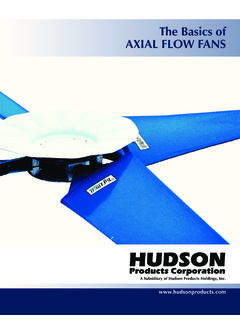
6 DESCRIPTIONOF AIR- CO OLEDHEATEXCHANGERSAnACHE is a dev iceforre jectingheatfroma fluiddirec tly to ambient in contrastto rejectingheat to wateran d thenrejecting it to air , aswith ashe ll andtub e heat exchangeran d a wetcoolingtower sys io us advantageof anACHEis thatit doesnotreq uire water,whichmeansthatplantsrequ iringlargecoolin g capac iti esneednotbelocatedne ar a supplyof cooli maybe assmallasanautomobileradiatororla rgeeno ughto rejecttheheatof turbineexhauststeamcon densat io n froma 1,200 MWpower plant whi chwoul d requi re 42modules,each 90feetwideby180fe et lo ngandservedbytwo60-footdi ameterfa nsdr iven by500 consi st s of thefollowingcomponents:(See Figure1): Oneor mor e bundlesof heattransfersur face.
7 An air-moving device,suc h asa fan,blower,orsta ck. Unl essit is na tur al draft,a driverandpowertra nsmis sion to mechanicallyrotatethefanorblower. A plenu m betweenthebundleorbundlesandtheair-movin g devic e. A sup port structurehighenoughto all owai r toent er benea th th e ACHE at a reasonable ra te . Optio nal header andfanmai nt enance walkwayswit h ladde rs to grade. Optio nal lou vers forprocessoutlettemperaturecon tr ol. Optio nal re cir culationductsandchambers forprotectio n again st freezingorsolidifica tionof highpou r point fl uid s in col d weather.
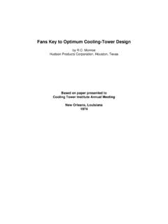
8 Optio nal varia blepi tchfanhubfortempera turecon tr ol and power tu be bun dle is an assembly of tubes,heade rs,sidefr ames, and tu be supportsasshownin lly thetu be surfaceexposedto thepa ssage of airhasext ended sur fa cein the formof finstocompe nsa te for th e lowheat tr ansferrat e of ai r atatmosp heric pre ssureandat a lo w enoughvel ocity forre aso na ble fan power e primetu be is usuallyroundandof anymetalsu it able fo r th e pro cess,dueconsider ati onbe inggivento corro sion, pre ss ur e, andtemperatureli mi ta ti s arehelic al or pl atetype,andareusuall y ofalu mi num fo r re asonsof goodthermalconductiv it yandeco nomy of eelfi nsareus edforve ry hig h tempera ture Fa n2.
9 Fa n Rin g3. Pl enum4. Nozzle5. Header6. Tu beBun dleINDUCEDDRAFTFORCEDDRAFT7. Dr iveAss embly8. Column Su pport9. Inlet Bell12934546786454312978 TypicalComponentsof an Air-CooledHeatExchangerHuds on Products Corpor ati onSugar Land,Texas, USAFig ure 1316163931286410513141571112163931181764 10131415181711121. TubeSheet2. Pl ugSheet3. TopandBottom Pla tes4. EndPlate5. Tube6. Pass Partition7. Stiffener8. Pl ug9. Nozzle10. SideFra me11. Tu beSpa cer12. Tu beSupportCr oss- member13. Tu beKee per14. Vent15. Dr ain16. Instru ment Conne ct ion17.
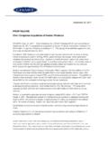
10 Cover Plate18. GasketPLUGHEADERCOVER PLATEHEADERT ypicalConstructionof TubeBundleswithPlugand CoverPlateHeadersHu dson Products Cor porationSug ar Land,Tex as, USAFig ure 24 Finsar e attachedto thetubesin a numberof ways:1) by anex tr usionpr ocessin which thefinsareex tr ud edfromthe wallof analuminumtu bethat is int egral ly bo ndedto thebase tubeforthefu ll le ng ) by he lic al ly wrappinga strip of aluminumtoembe d it in a pre-cut helicalgrooveandthenpeening ba ckthe ed gesof thegroove againsttheba seof thefin to tightlysecureit, or3) by wr ap pi ngon analuminumstr ip thatis footedat thebaseasit is wr sho wsa cu tawayviewof messerrat io nsarecutin th e airboundarylayer, whichincreasesturbulencewhichin turnincreasestheai r- sideheattr ansfercoeffici en t witha modestincreasein theair-sidepressu re dro p e choiceof fin typesis fl uen ce d bycos t, operatingte mperatures,andtheatmos pheric an sf er andpres suredropcharacteristics.