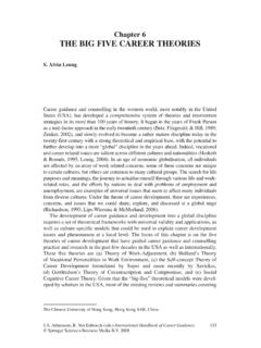
Transcription of Theories of Failure - Memorial University of Newfoundland
1 Theories of FailureStrength of a material or Failure of the material is deducedgenerally from uni-axial tests from which stress straincharacteristics of the material are typical stress-strain curves for ductile and brittle materialsare shown strength parameters are ORySuSTheories of FailureIn the case of multidimensional stress at a point we have a morecomplicated situation present. Since it is impractical to test everymaterial and every combination of stresses 1, 2,and 3,afailure theory is needed for making predictions on the basis of amaterial s performance on the tensile test., of how strong it willbe under any other conditions of static theory behind the various Failure Theories is thatwhateveris responsible for Failure in the standard tensile test will also beresponsible for Failure under all other conditions of of FailureThe microscopic yielding mechanism in ductile material isunderstood to be due to relative sliding of materials atoms withintheir lattice structure.
2 This sliding is caused by shear stresses andis accompanied by distortion of the shape of the part. Thus theyield strength in shear Ssyis strength parameter of the ductilematerial used for design used Theories for Ductile Materials are: Maximum shear stress theory Maximum distortion energy theory.(von Mises-Hencky s theory). Theories of FailureThe Maximum - Shear - Stress TheoryThe Maximum Shear Stress theorystates thatfailure occurs when themaximum shear stress from a combination of principal stresses equalsor exceedsthe value obtained for the shear stress at yielding in theuniaxial yielding, in an uni-axial test, the principal stresses are 1=Sy; 2=0and 3= the shear strength at yieldingSsy=[ 1-( 2or 3=0)]/2. ThereforeSsy=Sy/2 Theories of Failure (Maximum Shear Stress theory)To use this theory for either two or three-dimensional static stress inhomogeneous, isotopic, ductile materials, first compute the threeprincipal stresses ( 1, 2, 3) and the maximum shear stress 13as 12max2 = maxmin2pp Then compare the maximum shear stress to the Failure OR maxmin2ppsyS The safety factor for the maximum shear-stress theory is given bymaxsySN Theories of FailureDistortion-Energy Theory OR The von Mises - Hencky TheoryIt has been observed that a solid under hydro-static, externalpressure ( volume element subjected to three equal normalstresses)
3 Can withstand very large there is also energy of distortion or shear to be stored, as in thetensile test, the stresses that may be imposed are , it was recognized that engineering materials could withstandenormous amounts of hydro-static pressures without damage, it waspostulated that a given material has a definite limitedcapacity toabsorb energy of distortion and that any attempt to subject thematerial to greater amounts of distortion energy result in Strain Energy: Assuming that the stress-strain curve is essentially linear up to the yield point, we can express the total strain energy at any point in that range Uh be energy due to volume change and Udbe energy due to distortion. Then we can express each of the principal stresses in terms of hydrostatic component ( h), common to all the faces of volume element and distortion component ( id) that is unique to each volumetric change with no distortion, the terms in the bracket of eqn (g) must be zero.
4 Thus, we haveTheories of Failure Distortion energy theorystatesthat Failure by yielding under acombination of stresses occurs when the energy of distortion equalsor exceeds the energy of distortion in the tensile test when the yieldstrength is reached. According to theory Failure criteria isSy=[ 12+ 22+ 32- 1 2 3 ]1/2 For two dimensional stress state ( 2= 0), the equations reduces toSy=[ 12+ 32- 3 Theories of FailureIt is often convenient in situations involving combined tensile and shear stresses acting at a point to define an effective stress that can be used to represent the stress combination. The von-Mises effective stress( e) also sometimes referred to as equivalent stressis defined as the uniaxial tensile stress that would create the same distortion energy as is created by the actual combination of applied 22221231223311/ 22213311/ 22223eeexxyyxxyyxyyeIn terms of applied stresses in coordinate directionsSSafety factor N Static Failure Theories for Brittle Materials Brittle materials fracture than yield.]
5 Brittle Fracturein tension is considered to be due to normal tensile stress alone and thus the maximum normal-stress theory is applicable. Brittle fracture in compression is due to some combination of normal compressive stress and shear and Uneven Materials Some wrought materials, such as fully hardened tool steel, can be brittle. These materials tend to have compressive strength equal to their tensile strengths . They are called EVEN materials. Many cast materials, such as gray cast iron, are brittle but have compressive strengths much greater than their tensile strengths. These are called UNEVEN materials. For uneven materials; tensile strength is due to the presence ofmicroscopic flaws in the castings, which when subjected totensile loading, serve as nuclei for crack formation. when subjected to compressive stress, these flaws are pressedtogether, increasing the resistance to slippage from shearstresses.
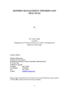
6 Gray cast irons typically have compressive strengths 3 to 4 timestheir tensile strengths and ceramics have even larger ratios. Another characteristics of some cast, brittle materials is that theirshear strength can be greater than their tensile strength , fallingbetween their compressive and tensile s circles for both compression and tensile tests of an evenand unevenmaterials are shown lines tangent to these circles constitute Failure lines for allcombinations of applied stress between the two circles. The areaenclosed by the circles and the Failure lines represent a safe the case of even material, the Failure lines are independent of thenormal stresses and are defined by the maximum shear strength ofthe is consistent with the maximum shear stresstheory. For the uneven material, the Failure lines are a function of both normal stresses and shearstresses.
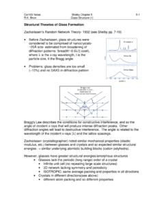
7 For compressive regime, as the normalstress component becomes increasinglynegative ( more compression) the material s resistance to shear stress increases. The interdependence between shear and normal stress is confirmed by experiment forcases where the compressive stress is dominant, specifically where the principal stresshaving the largest absolute value is compressive. However, experiments also show that in tensile-stress-dominated situations with uneven,brittle materials, Failure is due to tensile stress alone. The shear stress appears not to be afactor in uneven materials if the largest absolute value is Normal Stress TheoryThe maximum normal stress theory, shown for even materials could be used as the Failure criterion for brittle materials in static loading if compressive and tensile strengths were equal (even material).The maximum-normal stress theory envelope for an uneven material as the asymmetric square of half-dimensions Sut, - Sucis also shown.
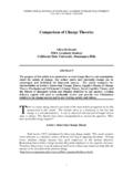
8 This Failure envelope is only valid in the first and third quadrants as it does not account for the interdependence of normal and shear stresses which affects second and fourth theoryThe coulomb-Mohr envelope attempts to account for the interdependence byconnecting opposite corners of these quadrants with Figure shows some gray cast-ironexperimental test data superposed on thetheoretical Failure envelopes. The failures in the first quadrant fit themaximum normal-stress theory line. The failures in the fourth quadrant fallinsidethe maximum normal-stress line(indicating its unsuitability) Also experimental data falloutsidetheCoulomb-Mohrline(indicatin gitsconservative nature).This observation leads to a modification of the Coulomb-Mohr theory to make it better fit the observed actual Failure data in the above figurefollow the even material maximum normalstress theory envelop down to a point Sut,-Sutbelow the 1axis and then follow a straight lineto 0, -Suc.
9 The set of lines shown by a solid lineis themodified-Mohr Failure theory is the preferred Failure theory for uneven, brittle materials in static are ordered 1> 3, 2= 0, then only thefirst and fourth quadrantsneed to be drawn asshown in Figurethe figure depicts threeplane stress conditionslabeled A, B, and A represents any stress state in which the two non zero principal stresses 1, 3are positive. Failure will occur when the load line OA crosses the Failure envelop at . The safety factor for this situation can be expressed asN = Sut/ 1A If the two nonzero principal stresses have opposite sign, then two possibilities exist for Failure , as depicted by points B and C. The only difference between these two points is the relative values of their two stress components 1,and 3. The load line OB exits the Failure envelop at above the point(Sut,-Sut)and the safety factor for this case is the same as the previous If the stress state is as depicted by point C, then the intersection of the load line OC and the Failure envelop occurs at below the point (Sut, -Sut).
10 The safety factor can be found by solving for the intersection between the load line OC and the Failure line and is given byIf the stress state is in the fourth quadrant both of these equations should be checked and the resulting smaller safety factor 113()ut ucucutSSNSS