Transcription of Theory Application and Sizing of Air Valves 4-7-15
1 1 Theory , Application , and Sizing of Air Valves VAL-MATIC VALVE AND MANUFACTURING CORP. 905 RIVERSIDE DRIVE, ELMHURST, IL 60126 TEL. (630) 941-7600 FAX. (630) 941-8042 2 AIR RELEASE VALVE Theory , Application , AND Sizing OF AIR Valves introduction One of the most misunderstood aspects of the water and wastewater industry is the presence of air in a pipeline and its impact on operations. Many operational problems, especially at the time of initial start-up, including damaged equipment, as well as faulty instrumentation readings, are blamed on inadequate thrust blocking, improper pipeline bedding, etc.
2 But in reality, many of these problems are not caused by improper installation of the line, but by failure to de-aerate the line. Properly de-aerating the pipeline will safeguard it from air-related problems. Air in a pressurized, operating pipeline has three primary sources. First, prior to start-up, the line is not empty; it is full of air. As the line fills, much of this air will be pushed downstream and released through hydrants, faucets, etc. but a large amount will become trapped at system high points. This phenomenon will occur because air is lighter than water and therefore, will collect at high points.
3 The second source of air is the water itself. water contains approximately 2% air by volume based on normal solubility of air in water . The dissolved air will come out of solution with a rise in temperature or a drop in pressure, which will occur at high points due to the increase in elevation. Finally, air can enter through mechanical equipment such as pumps, fittings, and Valves when vacuum conditions occur. Trapped air can have serious effects on system operation and efficiency. As air pockets collect at high points, a restriction of the flow occurs which produces unnecessary headloss and energy consumption.
4 A pipeline with many air pockets can impose enough restriction to stop all flow. Also, sudden changes in velocity can occur from the movement of air pockets. When passing through a restriction in the line such as a control valve, a dislodged pocket of air can cause surges or water hammer. water hammer can damage equipment or loosen fittings and cause leakage. Finally, corrosion in the pipe material is accelerated when exposed to the air pocket can result in premature failure of the pipeline. Air is sometimes removed from a line with a manual vent or fire hydrant during initial start-up but this method does not provide continual air release during system operation nor does it provide vacuum protection.
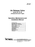
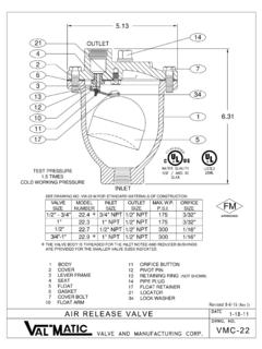
5 Today, municipalities use a variety of automatic air Valves at the pump discharge and along the pipeline. Three Basic Types of Air Valves There are three basic types of air Valves standardized in American water Works Association (AWWA) Standard C512: Air Valves for Waterworks Service. They are: * Air Release Valves * Air/Vacuum Valves * Combination Air Valves It is important to understand the functions and limitations of each valve type so that Valves can be located and sized properly for a pipeline. Air Release Valves Air Release Valves are probably the best known air valve and are typically furnished in sizes in.
6 (13 mm) through 3 in. (76 mm). The valve has a small precision orifice in the range of 1/16 in. ( mm) to in. (13 mm) to release air under pressure continuously during pipeline operation. The Air Release Valve 3 AIR/VACUUM VALVE has a float to sense the presence of air and a linkage mechanism that gives the float mechanical advantage in opening the orifice under full pipeline pressures. An Air Release Valve can also be used between a vertical turbine pump and a power actuated pump check valve to prevent surges in the piping between the pump and the check valve. In this Application , the opening of the check valve is delayed with a timer until the Air Release Valve can discharge the air in the pump column to achieve a controlled 1 to 2 ft/sec ( to M/sec) flow velocity in the pump column.
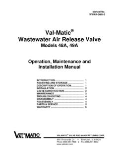
7 For a 20 foot (6 M) lift, the delay time will be about 10 to 20 seconds. Because the valve has limited vacuum flow capacity, a timer is also needed to delay the pump restart so that the water level in the pump column has time to return to its original level. Air Release Valves have a limited capacity for admitting and exhausting air. For this reason, most pipeline locations require both Air Release and Air/Vacuum Valves for exhausting and admitting large volumes of air. Air/Vacuum Valves An Air/Vacuum Valve is installed downstream of pumps and at high points to exhaust large volumes of air during pump start-up and pipeline filling.
8 The valve also will admit large volumes of air to prevent a vacuum condition from occurring in the pipeline and to allow for draining. A float in the valve rises with the water level to shut off the valve when the air has been exhausted. Upon the loss of pressure due to draining, line break, or column separation, the float will drop and allow air to reenter the pipe. It is important to note that under normal operation, the float is held closed by the line pressure and will not relieve accumulated air. An Air Release Valve is needed to relieve air during system operation. There are two variations of Air/Vacuum Valves that warrant discussion.
9 First, Air/Vacuum Valves can be equipped with an Anti Slam Device which controls the flow of water into the valve to reduce surges in the valve. The Anti Slam Device is useful at highpoints where column separation or rapid changes in velocity occur. Column separation can be predicted by computer transient analysis, but the following general guidelines can be used to help locate Anti-Slam Devices. 1. When the flow velocity is greater than 8 ft/sec ( M/sec), the surge potential can be as high as 400 PSI (2760 kPa). Also when the fill velocity exceeds 2 ft/sec ( M/sec) high surges can result.
10 2. High points where a vacuum forms on shut-off will exhibit rapid flow reversal. 3. Systems where the time for the water column to reverse exceeds the critical time will see high surges even from small changes in velocity. 4. Fast closing pump discharge check Valves may prevent slam but still cause line surges. 5. Systems with booster stations can see great fluctuations in line velocities on power failure. 6. If the pipeline discharge creates a siphon on shut-down, rapid flow reversal can be expected. Second, a Well Service Air Valve is an Air/Vacuum Valve equipped with a throttling device or an Anti Slam Device (4" and larger Valves ) for use with vertical turbine pumps.