Transcription of Thermal Management on SMD Thick Film Resistors …
1 vishay SFERNICEFilm ResistorsApplication NoteThermal Management on SMD Thick film Resistors ( dto25 , d2to20 , d2to35 )APPLICATION NOTE Revision: 27-Feb-151 Document Number: 52027 For technical questions, contact: DOCUMENT IS SUBJECT TO CHANGE WITHOUT NOTICE. THE PRODUCTS DESCRIBED HEREIN AND THIS DOCUMENTARE SUBJECT TO SPECIFIC DISCLAIMERS, SET FORTH AT Elyes GuezguezVishay has completed its range of Resistors using the Thick film technology. After the well-known Resistors RTO, LTO (TO-220 packages) for application with mounting on heatsink, three new surface mounted devices SMD Resistors are now available with the same technology: d2to20 (TO-263 / D2 PAK package) d2to35 (TO-263 / D2 PAK package) dto25 (TO-252 / DPAK package)The first one model can dissipate 20 W with 25 C case temperature.
2 d2to35 using the same packaging, is an improved version of d2to20 that can dissipate till 35 W with 25 C case temperature. Recently, another version was developed according the smaller TO-252 (DPAK) packaging. This new version can dissipate 25 W at 25 C for the case three Resistors offer a wide range of ohmic value, from to 550 k according the model of D2TO and from to 700 k for INTRODUCTIONTo achieve a high reliability level and performance of the Resistors , the board must be designed taking into account the Thermal consideration for each component. Each electronic component has a limitation about temperature of the die or the resistive element. This maximum temperature can be 150 C or 175 C, according the model.
3 Moreover, it is necessary to have a minimum distance between the different components used on a board. To realize a good design of the board, it is necessary to realize some evaluations and to know the Thermal environment of the document was written to help the designers during the conception of their board giving us some information about the Thermal dissipation for SMD components in order to use the resistor with optimum parameters. Evaluations of the maximum power for the three Resistors , d2to20 , d2to35 , and dto25 were realized in our laboratory, soldered on different boards using standard parameters in electronic PRESENTATION OF THE MEASUREMENTM easurements are realized with a Thermal IR camera.
4 The component is soldered on different boards using a lead-free alloy composition of each raw material used in these Resistors was adapted to be secure with the temperature of soldering. The customer is totally secure to use lead (Pb)-free alloy for the soldering of the component on the board with the standard temperature of 240 C to 270 C in accordance with the RoHS directive limiting the use of the lead (Pb).Main of our competitors are not able to propose Resistors with this configuration and require to not exceed 220 C on the case, so require to use Sn/Pb alloy. If this recommendation is not considered, the reliability of the component should decrease (dissipation, dielectric strength) due to some deteriorations of the internal the resistor is soldered, the board is positioned vertically in front of the Thermal IR camera.
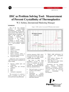
5 The ambient temperature during the test is 25 C. The voltage / power is applied on the component till reaching the maximum working temperature. After stabilization to the maximum temperature, the power is maximum working temperatures are listed according the different models of resistor :RESISTORMAX. WORKING TEMPERATURE OF THE RESISTIVE ELEMENTTHERMAL RESISTIVITY (RESISTIVE ELEMENT TO CASE): RTH (j - a)D2TO20155 C/WD2TO35175 C/WDTO25150 C5 C/WThermal Management on SMD Thick film Resistors ( dto25 , d2to20 , d2to35 )Application Sfernice Revision: 27-Feb-152 Document Number: 52027 For technical questions, contact: DOCUMENT IS SUBJECT TO CHANGE WITHOUT NOTICE. THE PRODUCTS DESCRIBED HEREIN AND THIS DOCUMENTARE SUBJECT TO SPECIFIC DISCLAIMERS, SET FORTH AT NOTEThe Thermal resistivity is calculated using the formula:RTH (j - c) + RTH (c - h) + RTH (h - a) are the Thermal resistances of the component, the soldering layer and of the board.
6 T is the difference between the maximum working temperature and the room temperature (25 C during the test).We can easily realize a comparison between the famous Ohm s Law and the heat dissipation. In this comparison, the temperature can be replaced by the voltage, the Thermal resistivity can be replaced by the resistance and the power by the current. We use this model to calculate the power or to calculate the different order to help you, we have measured the power applied for each different configurations Device / PC Board . Most of the PC board used FR4 and this material is limited by a maximum temperature due to its glass transition temperature (Tg): 130 C. Typically 20 C is the safety margin that the designers used for their Thermal LIMITATION OF THE PC BOARDThe PC board cannot be used with a temperature higher than the glass transition temperature Tg.
7 Higher than Tg, the characteristics of the board are deteriorated in particular for the Thermal conductivity. For FR4, this temperature is typically 125 C to 135 C. Engineers use often 20 C for a safety margin. So, we have two different limitations: The maximum working temperature of the resistor (from 150 C to 175 C depending on the model) and the maximum working temperature of the board (110 C). The first limitation in most applications, is the temperature of the can use different materials for the PC board with the following glass transition temperature (Tg): FR4 is standard for the electronic boards because it is less expensive, but more and more engineers use FR4 HTG / FR5 or IMS (Insulated Metal Substrate).
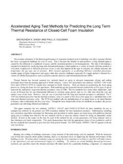
8 These new materials have a more important Thermal conductivity and a more important Tg (necessary due to the new lead (Pb)-free soldering process with higher temperature of soldering).Insulated metal substrate (IMS) consists of an aluminum metal baseplate covered by a thin layer of dielectric (usually an epoxy-based layer) and a layer of copper. Due to its structure, the IMS is a single-sided substrate, it can only accommodate components on the copper side. In most applications, the baseplate is attached to a heatsink to provide cooling, usually using Thermal grease and screws. Some IMS substrates are available with a copper baseplate for better Thermal CFR4125 C to 135 CFR4 HTG / FR5170 C to 180 CPolyimide260 CP TRTH (j - c) RTH (c- h) RTH (h - a) ++-------------------------------------- ---------------------------------------- --------------------=Tj: temp.
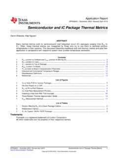
9 Resistive elementTa: ambient temp. or referenceTc: temperature caseRTH (j - c)RTH (c - a)TjTaPRTH (j - a)RTH (j - c)RTH (c - h)RTH (h - a)RTH (j - c): Thermal resistivity of the resistorRTH (c - h): Thermal resistivity of the soldering layerRTH (h - a): Thermal resistivity of the PC boardThermal Management on SMD Thick film Resistors ( dto25 , d2to20 , d2to35 )Application Sfernice Revision: 27-Feb-153 Document Number: 52027 For technical questions, contact: DOCUMENT IS SUBJECT TO CHANGE WITHOUT NOTICE. THE PRODUCTS DESCRIBED HEREIN AND THIS DOCUMENTARE SUBJECT TO SPECIFIC DISCLAIMERS, SET FORTH AT NOTE4. PRESENTATION OF THE SOLDERING PAD FOR D2TO AND DTOWe recommend the minimum footprints for the solderable contact area:Soldering Pad D2 TOSoldering Pad DTO5.
10 RESULTS OF THE TO INCREASE THE DISSIPATION ON A PC BOARD?The PC board are not very efficient for the heat dissipation: The Thermal resistivity can be typically 20 C/W to 100 C/W. For this reason, the board is often the limiting element for the dissipation of the component on the the example of a Thermal resistivity for the board of 35 C/W and if we use a limitation of 110 C with a standard FR4, the power that can be used on the board is: P = (TFR4 - Tamb)/RTH P = (110 - 25)/35 P = WIf we apply W on dto25 , we know that the Thermal resistivity of this resistor is 5 C/W, for TFR4 = 110 C on the board, we can calculate the temperature of the resistive element: TRes. - TFR4 = P x RTH = x 5 = TRes.