Transcription of Thermal mass Flowmeter t-mass S
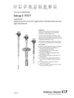
1 Technical InformationTI 0013A/05/ mass Flowmetert- mass SDirect mass Flow Measurement of GasesHauser+EndressThe Power of Know HowFeatures SMART technology permits two-way di-gital communication via HART protocol One standard, compact meter for all ga-ses with a process temperature rangeof +100 C Negligible pressure losses Single point measurement Wide turndown of up to 100:1 Every sensor is delivered with acalibration certificate traceable toNational StandardsFlexibility and Convenience t- mass measures the mass flow in theprocess. It can be programmed todisplay the flow rate in a wide range ofengineering units includingstandardised volume. Local, manual configuration is possiblewith the housing closed, even inhazardous areas Current and pulse simulation mode forcommissioning and diagnosis Insertion (AT70), flanged (AT70F) andwafer (AT70W) flowcell formatsprovide compatibility with any pipelineor ducting installations. Can be supplied to suit a wide range ofprocess pipe sizes and connections tosuit all areas of industry Display and the complete electronichousing can be rotated to enable thebest viewing anglesSafety CE mark compliance withelectromagnetic compatibilityaccording to EN50081-1:1992and EN50082-1:1992 Approved for hazardous areaoperation All meters hydrostaticallypressure-tested Sensor electronics featureself-diagnostics with alarm functionsApplicationst-massMeasuring SystemThe t- mass Thermal Flowmeter measuresthe mass flowrate of a wide range of gastypesApplications include: Natural gas flow to boilers and dryers Biogas from waste water plantdigesters Landfill gas monitoring Carbon dioxide metering in thebrewing and soft drinks industry Instrument air in process plants HVAC ducts Nitrogen, oxygen and argon flows inthe steel industry Gas production (eg.)
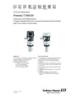
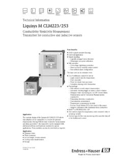
2 Ar, N2,CO2) Hydrogen flow in the chemical industry Leak detectiont- mass Flow SensorThe new t- mass S has the followingfeatures: Microprocessor-controlled Self-monitoring and diagnosis ofelectronics and sensor Separate wiring compartment for fieldconnections IP 65 protection type Built-in electromagnetic interferenceimmunity (EMC) Open collector pulse output Digital display with bargraph for rateand totalised flow (optional) All versions of the sensor are availablein compact form with the housingattached directly to the sensor andalso in remote form with the housingseparated from the sensor by up to100 metres Programming All functions can be set and all valuescan be read at the meter using fourpushbuttons, even in hazardous areas,and without opening the housing. A HARTTM hand-held device can beused to programme t- mass S via mA output, but is not requiredfor normal operation. t- mass S is deli-vered factory-programmed, but vie-wing or selection of the individual func-tions is easily done using a simplemenu and the local display, engi-neering units, current output functions,open collector function, system CommunicationThe SMART technology offered byt- mass S permits remote, two-way digitalcommunication Using a HARTTM handheldcommunicator or via any computersystem utilising a HARTTM interface Integration to higher level systems canbe accomplished using the optionalINTENSOR protocol (pending)t- mass AT 70 sensorused as an individualmeasuring pointA typical measuring system consists of: A t- mass S flow sensor A V DC power supply rated at 150 mA A current or pulse output signal for connection to an external indicator or measu-ring system ( PLC or SCADA)ti013y01 Typical application - Brewery carbon dioxidedistribution pipeline2 Meter BodyConstructionAT70 F Flanged Flowcell,(DN 15.
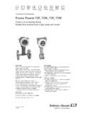
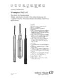
3 150, 1/2" .. 6") Integral straight pipework minimisesinstallation requirements andmaximises measuring performance Welded flange design, with a wide ran-ge of optional fittings. Optional degreasing for oxygen dutyAT70 W Wafer,(DN , 1" .. 4") This space-saving version fits betweentwo flanges with all nominal diametershaving the same 65 mm ( ") width. A mounting set assures fast andaccurate centering in the pipeline(see page 6). Optional degreasing for oxygen Insertion,( , 3" .. 39") Installed directly onto the pipework viaa variety of mounting stub flanged, screwed threadAll Versions Optional material traceabilitycertificate. Optional dye-penetrant Formats - All Versions Compact style with the electronic,display and keyboard attached to themain sensor body. Remote version with the electronics,display and keyboard housedseparately up to 100m (325 ft) awayfrom the measuring systemt-massChoice of remote andcompact housing formatsAT 70 InsertionDN80.
4 10003" .. 39"AT 70 WWaferDN25 .. 1001" .. 4"AT 70 FFlanged flowcellDN15 .. 1501/2" .. 6"ti013y02ti013y18 The t- mass family of sensors is available in a wide range of mechanical andhousing formats3 FunctionPlanningand InstallationPiping requirementsMeasuring PrincipleThermal metering is now a wellestablished method of mass flowmeasurement. It operates by monitoringthe cooling effect of a gas stream as itpasses over a heated flowing through the sensing sectionpasses over two PT100 RTDtransducers. One PT100 is usedconventionally as a temperature sensingdevice, whilst the other is used as a hea-ter. The temperature transducer moni-tors the actual gas processtemperature, whilst the self-heatedtransducer is maintained at a constantdifferential temperature (relative to themeasured gas temperature) by varyingthe current through it. The greater themass flow passing over the heatedtransducer, the greater the coolingeffect, and current required to keep aconstant differential temperature.
5 Themeasured heater current is therefore ameasure of the gas mass Measuring SensorEach AT 70 flow sensor has a four wireconnection. Two wires carry the powersupply and two wires transmit themeasured flow signal back to the controlroom either as a 4-20 mA current outputor as an open collector transistor pulseoutput. In addition the current outputconnection supports the HARTTM communication facility allowing remoteinterrogation of the flow, totalised flowand process gas temperature values aswell as configuration of the sensor is subjected to thorough ca-libration and test procedures and is supp-lied with an individual calibration certifica-te traceable to NationalStandardsThermal measuring principleView through the sensor pipe - t- mass AT 70 Wti013y19 The following installation recommendations should be observed as the minimumrequirements when installing t- mass in the and Outlet SectionsThe high sensitivity of the Thermal dispersion principle to low flow rates means the flo-wmeter can also be sensitive to internal disturbances in flowing gas steam (eg.)
6 Swirl)especially in the smaller pipe diameters (=<DN150, 6"). The installed Thermal flowsensor should therefore be installed as far as possibleupstream of any flowdisturbances. Disturbance sources can be split into two broad categories:Construction and/or Assembly construction practice should be followed at all times: Cleaned pipe and flange welded joints Correctly sized gaskets Correctly aligned flanges and gaskets The use of seamless pipe immediately upstream of the Flowmeter The use of pipework with a matching internal diameter to that of the Flowmeter toensure that no step disturbance greater than 1 mm ( ") can occur at the meterinlet or outlet. (3 mm [ "] for diameters > DN200 [8"]) As a general comment anything that disturbs the smoothness of the internalpipe wall within the dimensions stated on page 6 should be eliminated - the goalshould be a smooth uninterrupted internal Components or Pipework ConfigurationWhen disturbances (eg.
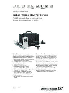
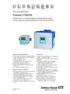
7 Pipe elbows, reducers, valves, T-pieces etc.) arelocated upstream of the Thermal meter, precautions must be taken to minimise anyeffects on the measuring figures on page 6 illustrate the minimum recommended upstream clear pipelengths expressed in multiples of the pipe diameter (x DN), longer lengths shouldalways be used if they are available in the metering of any other consideration the minimum recommendations for clearpipework on either side of the sensor are: Inlet sections:minimum15 x DN for the flanged flowcell (AT70F) x DN for the insertion (AT70) or wafer flowcell (AT70W) version. Outlet sections:minimum2 x DN for the flanged flowcell (AT70F) x DN for the insertion (AT70) or wafer flowcell (AT70W) : Where two or more disturbances are located upstream of the meter, the longestrecommended upstream pipe section is to be observed as anabsoluteminimum. It isalwaysrecommended to install control valves downstream of the Flowmeter . When an upstream disturbance is present whose disturbing effect cannot be rea-dily evaluated ( a dryer, other measuring device such as an orifice plate, turbinemeter, vortex meter), it is recommended to consider the disturbance in the sameway as a valve (see page 6).
8 For very light gases such as helium and hydrogen all recommendedupstream straight section values should be multiplied by two. Free-standing pipes subject to strong vibration should be firmly attached orsupported upstream and downstream of the ConditionerWith limited space and large pipes, it is not always possible to have the inlet sectionsgiven above. The specially developed AZT532 and AZT534 perforated plate flowconditioners in all but the most severe cases of pipeline disturbances allows thesensor to be installed in the pipework with reduced upstream clear distances. Referto page 11 for further Pulses/measuring AccuracyReciprocating pumps and some compressor systems can create strong changes inprocess pressure in the piping that can induce spurious internal flow patterns andthus cause additional measuring errors. These pressure pulses must be reduced bythe appropriate measures. Eg. Using expansion tanks With inlet expanders With a more suitable mounting locationPipework construction and assembly considerations - conditions to avoid5 Planningand InstallationAll versionsUpstream andDownstream piperequirementsti031y03 Inlet and outlet piping requirementsInsertion (AT70) and Wafer (AT70W) versionsInlet and outlet piping requirementsFlanged flowcell version (AT70F)ti013y06 Notes For very light gases such ashelium and hydrogen allupstream distancerecommendations should bedoubled.
9 The DN150 (6") sized flangedAT70F sensor requires theAZT532 flow conditioner typewhereas the DN25 to DN100(1" to 4") sizes require theAZT534 flow conditioner type. The Wafer (AT70W) andInsertion (AT70) versions requirethe AZT532 flow conditioner ty-pes regardless of line size. Flow conditioners are notavailable for all line sizes - checkpage 11 and with your E+H salesrepresentative beforeplanning your installation set for wafer version (AT 70W)Note the following points before mounting the AT70W sensor: The flowcell and wafer style meter bodies are protected against damage duringtransit by two protective disks. Remove both protective disks before installing theflowmeter in the pipeline. Take particular care that the internal diameters of any installed gaskets directlyupstream and downstream of the meter body are identical or larger than those ofthe meter body and/or process piping. Gaskets which protude into the flow willinvariably lead to metering SetTo ensure the accurate centering of wafer style meters with respect to the flangefitting on any pipework installation, it is essential for maximum performance that themounting set supplied with the sensor is mounting kit comprises A set of correctly sized fixing bolts Accurately dimensioned centering ringsMounting Procedure Place one centering ring over each side of the meter body Mount two or more bolts as required with washers on both piping flanges Adjust the sensor together with the two centering rings between the bolts alreadymounted and the piping flanges (including gaskets)
10 Mount the rest of the bolts Screw tight the bolts in a diagonal tightening patternPlanningand InstallationAT70 WWafer version only7 Sensor mountingdetailsAT70 AdjustableInsertion sensorInsertion depthRefer to page 20 for a guideline onspecifying the correct sensor length tosuit the pipe or duct size, the guidanceassumes that a standard AZT70mounting boss (see page 21) is any other type or size of mountingboss is used (eg. with an integral ball val-ve) then the installation must be measu-red to calculate the correctinsertion length which will subsequentlyallow the correct sensor length to becorrectly specified.(Refer to page 9 forfurther guidelines)..Flow mounting arrangementsa - Adjustable process length + flangeb - Adjustable process length + screw fittingWhen installing the sensor, the following three dimensions need to be taken into account toallow the correct insertion length to be specified: A = Internal diameter of the circular pipe or for a rectangular duct, the duct height if thesensor is to be mounted vertically or duct width if it is to be mounted horizontally B = Pipe wall thickness C = Depth of the mounting boss on the pipe or duct including the sensor fittingFor Insertion Sensors Fitted With An Adjustable Insertion Probe Depth (ie.)