Transcription of Thermocouple Theory - Pyromation
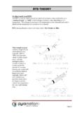
1 Thermocouple Theory Page 1 WHAT IS A Thermocouple ? In 1821, Thomas Seebeck discovered if metals of two different materials were joined at both ends and one end was at a different temperature than the other, a current was created. This phenomenon is known as the Seebeck effect and is the basis for all thermocouples. T1 T2 A Thermocouple is a type of temperature sensor, which is made by joining two dissimilar metals at one end. The joined end is referred to as the HOT JUNCTION. The other end of these dissimilar metals is referred to as the COLD END or COLD JUNCTION.
2 The cold junction is actually formed at the last point of Thermocouple material Positive leg Hot junction Cold Junction (Joined End) Negative leg Certain combinations of metals must be used to make up the Thermocouple pairs. If there is a difference in temperature between the hot junction and cold junction, a small voltage is created. This voltage is referred to as an EMF (electro-motive force) and can be measured and in turn used to indicate temperature.
3 The voltage created by a Thermocouple is extremely small and is measured in terms of millivolts (one millivolt is equal to one thousandth of a volt). In fact, the human body creates a larger millivolt signal than a Thermocouple . To establish a means to measure temperature with thermocouples, a standard scale of millivolt outputs was established. This scale was established using 32 deg. F (0 C) as the standard cold junction temperature (32 deg. F (0 C) = 0 millivolts output). Thermocouple Theory Page 2 COLD JUNCTION COMPENSATION As we mentioned earlier, the last point of Thermocouple material is known as the cold junction.
4 The amount of output the t/c produces is determined by the difference between the hot junction and the cold junction temperatures. The cold junction temperature must be known to accurately determine the temperature. Lets look at the following examples; If we had a Thermocouple in a heat treat furnace and wanted to know what temperature it was in that furnace, we could attach a voltmeter to the cold junction and measure the voltage. Let s say that the furnace is operating at 1000 deg. F. and it is 100 deg. F at the cool end of the T/C. Since we said that a T/C measures the difference between the hot and cold junctions, our formula would be: 1000 (hot junction) - 100 (cold junction) = 900 deg.
5 F. There seems to be a problem since we said that the furnace was at 1000 deg. F. This brings us to COLD JUNCTION COMPENSATION. COLD JUNCTION COMPENSATION is usually done automatically by the measuring instrument. The instrument measures the temperature at the cold junction and adds it back to the equation. 1000 (hot junction) - 100 (cold junction) = 900 deg. F + 100 deg. F (cold junction temp) = 1000 deg F This way the instrument indicates the actual temperature of the hot junction. This COLD JUNCTION compensator is usually located at the terminals on the back of the indicating instrument and you must maintain T/C material all the way to this point.
6 For a Thermocouple to function properly, there must be no other metals used between the hot junction and the cold junction. If wire is needed to connect the T/C to the indicating instrument, the leadwire must be made of the same material as the T/C. It is acceptable to use terminal blocks and lugs made of plain copper in a Thermocouple circuit as long as the positive and negative terminals are at the same temperature. (Example: terminal blocks in heads or spade lugs on wire) If you were to use plain copper wire instead of T/C extension wire to run to the instrument, your cold junction would be formed at the junction between the copper and the T/C wire.
7 This junction would most likely not be at the same temperature as the back of the instrument where the compensator is located. This would then create an error in the indicated temperature. Thermocouple Theory Page 3 If a customer were to use the wrong T/C extension wire, the same problem could appear. This is why we must use the correct T/C extension wire on our assemblies. It is also acceptable to have a third metal in the hot junction as long as that metal is at the same temperature as the Thermocouple material. REFERENCE TABLES There are printed tables that show the temperature vs.
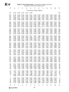
8 Millivolt output figures. These reference tables are all based on the cold junction being at the freezing temperature of water (32 deg F or 0 deg C). We use these tables in our Certification Lab along with ice baths to make our cold junctions at 32 deg. F. Based on ASTM E-230 Thermocouple TYPES All thermocouples have a corresponding color code per ASTM E-230 (replaces ANSI ) Consult the Pyromation catalog page GEN-6 for a complete list of American color codes BASE METAL THERMOCOUPLES Base metal thermocouples are known as Types E, J, K, T and N and comprise the most commonly used category of Thermocouple .
9 The conductor materials in base metal thermocouples are made of common and inexpensive metals such as Nickel, Copper and Iron. Type E: The Type E Thermocouple has a chromel (Nickel-10% Chromium) positive leg and a Constantan (Nickel- 45% Copper) negative leg. Type E has a temperature range of -330 to 1600 F, has the highest EMF Vs temperature values of all the commonly used thermocouples, and can be used at sub-zero temperatures. Type E thermocouples can be used in oxidizing or inert atmospheres, and should not be used in sulfurous atmospheres, in a vacuum or in low oxygen environments where selective oxidation will occur.
10 The color code for TYPE E wire is purple and red. Type J: The Type J Thermocouple has an Iron positive leg and a Constantan negative leg. Type J thermocouples can be used in vacuum, oxidizing, reducing and inert atmospheres. Due to the oxidation (rusting) problems associated with the iron leg, care must be used when using this Thermocouple type in oxidizing environments above 1000 F. The temperature range for Type J is 32 to 1400 F and it has a wire color code of white and red. Thermocouple Theory Page 4 Type K: The Type K Thermocouple has a chromel positive leg and an Alumel (Nickel- 5% Aluminum and Silicon) negative leg.