Transcription of THERMOFORMING HIGH DENSITY POLYETHYLENE …
1 THERMOFORMING high DENSITY POLYETHYLENE SHEET USING TEMPERATURE-CONTROLLED ALUMINUM TOOLING Brett K. Braker, Pennsylvania College of Technology Abstract Previous research has shown that THERMOFORMING high DENSITY POLYETHYLENE (HDPE) is something that has been shied away from in the plastics industry. This paper will show the differences of THERMOFORMING HDPE using temperature-controlled and non temperature-controlled tooling. In doing that, it will aim to prove that HDPE can be used with success in the THERMOFORMING industry, as long as temperature controlled aluminum tooling is used. Individual Performance Objectives 1. Show the importance of temperature-controlled molding in THERMOFORMING . 2. Prove that HDPE can be a relevant material to use in THERMOFORMING , instead of just amorphous materials. Introduction high DENSITY POLYETHYLENE isn t usually thought of as a usable material when THERMOFORMING is talked about. It is not a material that seems like it would work with that type of process.
2 Companies in industry have shied away from HDPE, because of its crystallinity and shrinkage rate. The THERMOFORMING industry almost always uses amorphous materials, because they are a lot easier to control than crystalline materials. Also, a lot of companies use wooden or urethane tooling to run their parts, because it is a lot cheaper to do that than to get aluminum or steel tooling. Instead of heating up their mold with water or oil, and keeping it at a constant temperature, they will just let the heat of the machine and material heat up the mold over time, but will run into problems at the start and end of their runs. The mold will either be too cold for the material and cool it too quickly, or be too hot, which will lengthen cycle time, and increase the chances of part defects. Increased cycle times and part defects will cost the company a lot of money in the long run, when they could ve just used a temperature-controlled aluminum mold.
3 A temperature-controlled mold will stabilize mold temperature from the start, and will not have the variation a non temperature-controlled mold will. This will give the company much needed control of the tooling to help give them a chance at producing better quality parts for their customers. With better quality parts coming off of the temperature-controlled mold, there will be much less scrap sheet, stabilized cycle times and oven temperatures , and the company will be paying the cost of the tooling off with material savings. Temperature-controlled tooling opens the doors to numerous materials that were once thought to never have a place in the THERMOFORMING industry. It minimizes the increase in percent crystallinity that a material goes through when it is heated up and let to relax. Material Black HDPE sheet was used for this project. The sheet was 40 inches wide (machine direction), inches long (transverse direction), and inches thick.
4 The material has a levant finish on one side and a smooth finish on the other, which would be the side used to touch the mold. The HDPE should be formed in between 285 and 385 degrees Fahrenheit, with the optimum forming temperature being 330 degrees Fahrenheit. The optimum temperature to take the sheet out of the mold is 170 degrees Fahrenheit. Thermoformable high DENSITY POLYETHYLENE sheet has an average DENSITY of pounds per inch cubed ( grams per cubic centimeter). It also has a average Shore D Hardness, an average ultimate tensile strength of 3,800 pounds per square inch (psi), and an average tensile yield stress of 3,829 psi. The average deflection temperature with 66 psi is degrees Fahrenheit. Procedure This project started when the material was received from the manufacturer. The first step after receiving the material was to put a grid system on the smooth side of the sheet, so that it could be measured to show the stretching that the material goes through when it is formed.
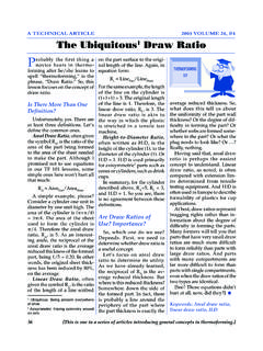
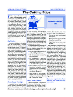
5 With help from the Printing Department at Penn College, the sheet was screen printed with an inch by inch silver grid system (shown in Figure 1). After the gridding was complete on the 50 HDPE sheets that were available for the project, they were ready to be thermoformed. The first mold that was to be used on the project was a replica mold of the main aluminum mold for the project, and it was made out of Renshape 472 medium- DENSITY Polyurethane Modeling Board. The mold has a wooden base, and then the machined polyurethane is made to be exactly the same Figure 1 (gridding system on sheet after being formed) dimensionally as the aluminum mold, which in relation to the material, is inches long, inches wide, and inches high . The mold was first set on the lower platen (shown in Figure 2) of the MAAC Thermoformer that was used on the project. The first set of parts that were made on the machine was to try and help set up a process that would produce a quality part, so that a production-style run could be started.
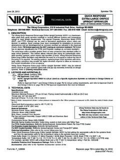
6 After a few parts were formed, it was easily determined that the mold should be hung from the top platen rather than the bottom platen. Figure 2 (Renshape mold on bottom platen) The mold was switched from being set on the bottom platen to being hung from the top platen, because the sag in the pliable material coming from the oven coinciding with the top of the cool mold would cause a build-up of material in the four corners where the material would drape over the side of the mold. Switching to the top platen (shown in Figure 3) would eliminate the build-up of material in the corners, and create a better quality part. Also by switching to the top platen, counter material sag stretching was eliminated. When a material is run in a THERMOFORMING machine with the mold set on the bottom platen, the sag of the material as it comes out of the oven is met by the mold coming up into the pliable sheet and going through it to help create a seal to be able to vacuum the sheet around the dimensions of the mold.
7 This phenomenon stretches the material twice, which could lessen some of the material s important physical properties. If the properties are compromised, the part has a possibility of failing once it gets out to its customer and starts being used. Hanging the mold from the top platen eliminates this from happening to the material. With the mold coming from the top of the sagging material, there is only one stretch on the material, which is in the same direction of the sag, and then the vacuum created by the seal between material and mold sucks the material back to the shape of the mold. This type of molding minimizes the stress on the material and theoretically eliminates the extra physical property damage done by double stretching with molds set on the bottom platen. Figure 3 (Renshape mold on top platen) After the urethane mold was hung from the top platen, the machine settings were altered so that they were the exact same as the bottom platen settings and it was time again to try and find the correct settings and cycle to produce quality parts repeatedly.
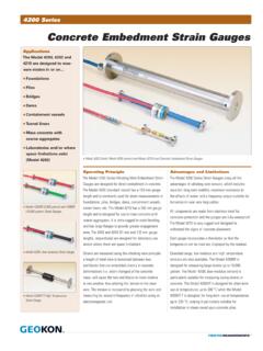
8 Once they were found, a production-style run could be performed. A few problems were run into when trying to find the perfect cycle. The first problem was that the rails that hold the sheet in place were set too close to the mold and the mold was going too far through the rails. This caused the back of the sheet to rip out completely. After this, the rails were moved out to about one-half inch from the mold and the mold was programmed so that it didn t go through the rails as far. The top of the mold was then set to go down inches from the sheet in the rails. The sheet didn t rip completely when the mold came down through it, but it did leave a few small tear spots, which were a sign of the side of the sheet closest to the oven being too hot when it came out to be formed (shown in Figure 4). This problem was fixed by lowering the oven percentages in the back of the oven so that part of the sheet wouldn t be as hot as it exited the oven.
9 After the cycle was finalized, the production-style run was ready to be started. A production-style run is basically just a certain number of sheets run one right after another. This production run was set for 10 sheets, and there were a number of variables that were measured related to the machine during the production run. They were: temperature of the front of the mold, the top of the mold, Figure 4 (Tears in back of formed sheet) and the back of the mold (all of which were taken right before the next sheet in the run was loaded in the rails), sheet temperature as it came out of the oven right before forming, and temperature of the sheet after the rails opened after cooling and the formed part was ready to be taken out of the machine. Room temperature and humidity were also measured before every sheet was loaded. After the formed sheet came out of the mold, it was set into the measuring jig that was made for the dimensions of what the sheet should be as it comes off the mold.
10 The aluminum jig (shown in Figure 5) is inches wide and inches long. The sheet was placed in the jig the exact same way every time, and measured in 10 different places along the lengths and widths of the part (shown in Figure 6) using dial calipers set at the edge of the jig and being extended into the formed sheet. Figure 5 (HDPE sheet in aluminum jig) Also shown in Figure 5 is how thickness measurements were taken on each of the sheets after they had been measured using the jig. A drill and hole saw attachment were used to cut one-inch holes in the top, front, left, back, and right sides of the sheet. The discs that were produced were then measured for thickness. Figure 5 also shows that the holes were drilled in the left side of each side immediately after the sheet was taken out of the machine. Measurements taken 24 or more hours later were drilled out of the right side of each side.