Transcription of Thermostatic Steam Traps MK with Membrane ... - …
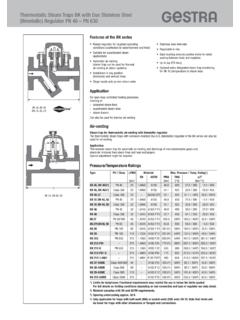
1 Thermostatic Steam Traps MK. with Membrane Regulator PN 25 PN 40. Features of the MK series With tandem seat (double sealing). for low condensate flowrates Very sensitive response characteristic Built-in non-return valve (only MK 45). Function is not impaired by Stainless steel internals (corrugated Membrane high back pressure of Hastelloy). Automatic air-venting (trap can be used Design U with undercooling capsule: for thermal air-venting in Steam systems). utilization of a certain amount of s ensible heat Installation in any position by banking-up of condensate, d ecreasing the (horizontal and vertical lines) amount of flash Steam High hot-water capacities even with low Optional extra: Integrated condensate monitoring differential pressures for MK 45 (temperature or Steam loss). L Application MK 45-1 Type DN 15, 20, 25. MK 45-1 With tandem seat (double sealing). MK 35/31 1) For low condensate flowrates, Steam -tracing, Steam -line drainage, air-venting MK 45-2 With single seat MK 35/32 1) For medium condensate flowrates, Steam -tracing, drainage of heat exchangers, air-venting MK 25/2 1) With single seat MK 25/2 S 1) For large condensate flowrates, MK 35/2 S 1) drainage of heat exchangers MK 35/2 S3 1).
2 MK 36/51 1) With tandem seat (double sealing) with flat gasket SS. MK 36/52 1). I N LE For small/large condensate flowrates, Steam tracing, Steam -line drainage, A EL venting and vacuum-breaking. Also suitable for food, biological and ST STE pharmaceutical applications. MK 45 A-1 SS For small and large condensate flowrates; Steam -tracing, MK 45 A-2 I N LE Steam -line drainage, air-venting A EL. L. MK 35/31, DN 10, 15 ST STE. 1) Can also be used for vacuum breaking (aerating). Air Venting Steam Trap for Thermostatic Air-Venting with Membrane Regulator The Thermostatic Steam Traps with Membrane regulators of the MK series can also be used for air-venting. Application Thermostatic Steam trap for automatic air-venting and discharge of non-condensable gases and Steam /air mixtures from Steam lines and heat exchangers. A special type of Membrane regulator capsule might be required.. Pressure/Temperature Ratings Type PN / Class PMX Material Max.
3 Pressure/Temp. Rating1). EN ASTM PMA TMA p/T. L [bar] [bar] [ C] [bar/ C]. MK 35/2 S, DN 25 MK 35/31, MK 35/32 PN 25 21 A105 400 / 225 / 400. MK 45-1, MK 45-2 PN 40 32 A105 450 / 300 / 450. MK 45-1, MK 45-2 Class 300 32 A105 425 / 300 / 425. MK 35/2 S, DN 25. PN 40 32 A105 450 / 300 / 450. MK 35/2 S3, DN 25. MK 25/2, A105/. MK 25/2 S, PN 40 32 450 / 300 / 450. A216-WCB. DN 40, 50. MK 36/51, EE SS. 32 ) A479-F304 400 / 250 / 400. MK 36/52. ST INLE. L. A. MK 45 A-1, ST. PN 40 32 A182-F316L 400 / 300 / 4003). MK 45 A-2. EE SS. ST LE. L. N. MK 45 A-1, AI. Class 300 32 A182-F316L 400 / 300 / 4003). ST. MK 45 A-2. 1) Limits for body/cover. Functional requirements may restrict the use to below the limits quoted. L For full details on limiting conditions depending on end connection and type of regulator see data sheet. MK 35/2 S 3, DN 25 2) EN material comparable to ASTM material. 3) If the operating temperatures exceed 300 C intercrystalline corrosion may occur.
4 Do not subject the equipment to operating temperatures higher than 300 C unless intercrystalline corrosion can be ruled out. Thermostatic Steam Traps MK. with Membrane Regulator PN 25 PN 40. Available End Connections and Overall Length Overall length (L) in mm Type Connection DN 8 DN 10 DN 15 DN 20 DN 25 DN 40 DN 50. 1/4" 3/8" 1/2" 3/4" 1" 11/2" 2". MK 45-1 Flanged EN PN 40 150 150 160 . MK 45-2 Flanged ASME 1501) 150 150 160 . MK 45 A-1 LESS Flanged ASME 3001) 150 150 160 . STAIN EL Screwed sockets MK 45 A-2 ST E 95 95 95 . L MK 35/2 S3 only DN 25 Socket-weld (SW) 95 95 95 . MK 25/2 , DN 40, 50 MK 35/2 S only DN 25 Butt-weld (BW) 2) 200 200 200 . MK 35/31 Screwed sockets 70 70 . MK 35/32 Socket-weld (SW) 95 . MK 25/2 DN 40 50 Flanged EN PN 40 230 230. MK 25/2 S DN 40 50 Flanged ASME 150 230 230. Flanged ASME 300 230 230. Screwed sockets 130 230. Socket-weld (SW) 130 230. MK 36/51 Screwed sockets 65 65 65 65 . MK 36/52 SS Union butt-weld INLE 150.
5 L STA EEL nipples 3). MK 25/2 S, DN 40, 50 ST Hinged clamp 65 65 65 65 . 1) MK 45 with ASME. flanges: overall length 172 mm available on request. 2) Only MK 45. 3) Made of carbon steel or stainless L. L. L. steel MK 36/51, DN 15 mm MK 36/51, DN 8, 10, 15, 20 mm MK 36/51, DN 8, 10, 15, 20 mm Design with union Connection: Connection: screwed socket butt-weld nipples hinged clamp Capacity Charts The charts show the maximum hot condensate capacities. MK 45-1/MK 45A-1 (Curve 4) MK 35/31 (Curve 1) MK 25/2 S, DN 40, 50 (Curve 1) MK 35/2 S3, DN 25 (Curve 3). MK 45-2/MK 45A-2 (Curve 5) MK 35/32 (Curve 2) MK 25/2, DN 40, 50 (Curve 2) MK 35/2S, DN 25 (Curve 4). MK 36/51 (Curve 3) MK 36/52 (Curve 2). [lb/h] [kg/h]. 20000 9000. 1. 8000. 6000 2. 10000. 4000. 8000. 3. 6000 3000. 2000. 4000 4. 3000. 1000. 2000. 800. 600. 1000. 800 400. 300. 600. 500. 200. 400. Durchfluss Capacity Capacity 300. Capacity 200 100. 0,6 0,8 1 2 3 4 5 6 8 10 22 32 [bar].
6 0,6 0,8 1 2 3 4 6 8 10 22 32. [psi]. 8 10 20 30 40 60 80 100 200 300 465. 8 10 20 30 40 60 80 100 200 465. Differential pressure Differenzdruck Differential pressure Differential pressur