Transcription of Thermowell with flange Model TW10 - WIKA
1 TemperatureThermowell with flangeModel TW10 Thermowell with flange , Model TW10 Applications Petrochemical industry, on-/offshore, plant construction For high process loads For high chemical demandsSpecial features Heavy-duty design Coating for corrosive or abrasive process loads Possible Thermowell forms: tapered, straight, stepped Design TW10-F:Full penetration weld versionDesign TW10-P, TW10-R: with double weld seamDesign TW10-S, TW10-B:Screw-welded designWIKA data sheet TW 1 of 6 WIKA data sheet TW 01/2022 DescriptionEach Thermowell /protection tube is an important component of any temperature measuring point. It is used to separate the process from the surrounding area, thus protecting the environment and operating personnel and keeps aggressive media, high pressures and flow rates from the temperature sensor itself and thereby enables the thermometer to be exchanged during on the almost limitless application possibilities, there are a large number of variants, such as Thermowell /protection tube designs or materials.
2 The type of process connection and the basic method of manufacture are important design differentiation criteria. A basic differentiation can be made between threaded and weld-in thermowells/protection tubes, and those with flange , one can differentiate between protection tubes and thermowells. Protection tubes are constructed from a tube, that is closed at the tip by a welded solid tip. Thermowells are manufactured from TW10 series of thermowells with flange connection are suitable for use with numerous electrical and mechanical thermometers from to the heavy-duty design, these international design thermowells are the first choice for use in the chemical and petrochemical industries and in plant 2 of 6 WIKA data sheet TW 01/2022 SpecificationsBasic informationThermowell form Tapered Straight SteppedVersionsDesign TW10-FFull penetration weld versionDesign TW10-PWith double weld seam (weld seam strength 3 mm)Design TW10-RWith double weld seam (weld seam strength 6 mm)Design TW10-SScrew-welded design, weld seam does not come into direct contact with the mediumDesign TW10-BScrew-welded design, additional weld seam on the process side (sealing joint)Material (wetted)
3 Stainless steel 304/304L Stainless steel 316/316L Stainless steel Stainless steel A105 Alloy C4 Alloy c276 Alloy 400 Titanium grade 2 1) Tantalum sheet for wetted partsOther materials on requestCoatingHardfacing for abrasive process loads with Stellite 6 Laser claddingLayer thickness mm [ in] (standard)Higher layer thickness on request Plasma Transfer Arc (PTA)Layer thickness mm [ in] (standard) up to mm [ in] Air Plasma Spraying (APS)Layer thickness max. mm [ in] High Velocity Oxide Fuel (HVOF)Layer thickness mm [ in]Corrosion protection for high chemical loads P FALayer thickness min. mm [ in] (standard) or min. mm [ in] (special design) ECTFE (Halar )Layer thickness min. mm [ in]Other resistant coatings on request1) For titanium grade 2 material in a washer disc construction, the blind flange is designed to be is a registered trademark of the company Kennametal ECTFE is a registered trademark of the company Solvay for coatingsHardfacing:Laser cladding ( Thermowell stem)Hardfacing:Air Plasma Spraying (APS), Thermowell stemCorrosion protection:PFA (wetted parts)Page 3 of 6 WIKA data sheet TW 01/2022 Process connectionType of process connection flange per ASME flange per EN 1092-1 flange per DIN 2527 Other flanges on requestConnection to thermometer NPT female thread G female thread M20 x dimensions on requestBore size B mm [ in] mm [ in] mm [ in] mm [ in] mm [ in] mm [ in] mm [ in] mm [ in] mm [ in]Insertion length U13.
4 1,575 mm [ .. 62 in]Connection length H 57 mm [ in] 83 mm [ in]Other connection lengths on requestTip mm [ in]Other tip thicknesses on requestSuitable stem lengths l1 (dial thermometer) with tip thickness mm [ in]Connection design S, 4 or 5l1 = U + H - 10 mm [ in]Connection design 2l1 = U + H - 30 mm [ in]Sealing face roughnessVersionAARH in inchRa in mRz in mASME finish125 .. finish< 125< TJ< 63< < 125< 1092-1 Form .. 50 Form .. 2527 Form C--40 .. 160 Form E--< 16 Operating conditionsMax. process temperature, process pressureDepending on: Thermowell design- Dimensions- Material- Coating- flange pressure rating Process conditions- Flow rate- Density of mediumWake frequency calculation (option)Per ASME PTC TW-2016 recommended in critical applications as a WIKA engineering service For further information see Technical information IN Wake frequency calculation.
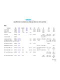
5 V BdHU QN BTtTW10-P: 3 mm [ in]TW10-R: 6 mm [ in]H Q B Bd NUTt V1 NPTUHTt V1 NPT Q B BdN V BdHTtU QN BPage 4 of 6 WIKA data sheet TW 01/2022 Dimensions in mm [in]Design TW10-FDesign TW10-SDesign TW10-P, TW10-RDesign TW10-B1) For technical reasons around the 1 NPT thread, the connection length, H, and also the insertion length, U, can move with a tolerance of 5 mm [ in] to the specified nominal flush connection of the thread with the flange sealing face can therefore not be seamweld seamweld seam1)1)1)1) in lbsDimensions in mm [in]Weight in kg [lbs] (approx.)H Q VU = 4"U = 13"U = 22"1"150approx. 57 [2 ]22 [ ]16 [ ] [ ] [ ] [ ]300approx. 57 [2 ]22 [ ]16 [ ] [ ] [ ] [ ]600approx. 57 [2 ]22 [ ]16 [ ] [ ] [ ] [ ]1,500approx. 83 [3 ]22 [ ]16 [ ] [ ] [ ] [ ]2,500approx. 83 [3 ]22 [ ]16 [ ] [ ] [ ] [ ]1 "150approx. 57 [2 ]25 [ ]19 [ ] [ ] [ ] [ ]300approx. 57 [2 ]25 [ ]19 [ ] [ ] [ ] [ ]600approx.
6 57 [2 ]25 [ ]19 [ ] [ ] [ ] [ ]1,500approx. 83 [3 ]25 [ ]19 [ ] [ ] [ ] [ ]2,500approx. 83 [3 ]25 [ ]19 [ ] [ ] [ ] [ ]2"150approx. 57 [2 ]25 [ ]19 [ ] [ ] [ ] [ ]300approx. 57 [2 ]25 [ ]19 [ ] [ ] [ ] [ ]600approx. 57 [2 ]25 [ ]19 [ ] [ ] [ ] [ ]1,500approx. 83 [3 ]25 [ ]19 [ ] [ ] [ ] [ ]2,500approx. 108 [4 ]25 [ ]19 [ ] [ ] [ ] [ ] Bd BNHU V QTt3 mm [ in]3 mm [ in]Page 5 of 6 WIKA data sheet TW 01/2022 Design TW10-P in washer disc constructionLegend:HConnection lengthUInsertion lengthNConnection to thermometer BBore size QRoot diameter VTip diameter BdBar diameter (depending on selected root diameter or customer specification)TtTip thickness ( mm [ in]) flanges, tapered Thermowell formDNPN in barDimensions in mm [in]Weight in kg [lbs] (approx.)H Q VU = 160 mmU = 500 mm254045 [ ]22 [ ]16 [ ] [ ] [ ]63/6445 [ ]22 [ ]16 [ ] [ ] [ ]10045 [ ]22 [ ]16 [ ] [ ] [ ]404045 [ ]25 [ ]19 [ ] [ ] [ ]63/6445 [ ]25 [ ]19 [ ] [ ] [ ]10045 [ ]25 [ ]19 [ ] [ ] [ ]504045 [ ]25 [ ]19 [ ] [ ] [ ]63/6445 [ ]25 [ ]19 [ ] [ ] [ ]10045 [ ]25 [ ]19 [ ] [ ] [ ]804060 [ ]25 [ ]19 [ ] [ ] [ ]63/6460 [ ]25 [ ]19 [ ] [ ] [ ]10060 [ ]25 [ ]19 [ ] [ ] [ ]1004060 [ ]25 [ ]19 [ ] [ ] [ ]63/6460 [ ]25 [ ]19 [ ] [ ] [ ]10060 [ ]25 [ ]19 [ ] [ ] [ ]WIKA Alexander Wiegand SE & Co.
7 KGAlexander-Wiegand-Stra e 3063911 Klingenberg/GermanyTel. +49 9372 132-0 Fax +49 9372 ENPage 6 of 6 WIKA data sheet TW 01/2022EN and DIN flanges, tapered Thermowell form - only for design TW10-P and TW10-R(only for welding version with weld seam, 3 mm [ "] or 6 mm [ "] on both sides) 04/2008 WIKA Alexander Wiegand SE & Co. KG, all rights specifications given in this document represent the state of engineering at the time of reserve the right to make modifications to the specifications and informationModel / Thermowell form / Thermowell material / flange material / Head diameter / Connection to the thermometer / Bore B / Nominal diameter DN / Pressure rating PN / Sealing face / Wall thickness of flange nozzle / Insertion length U / Connection length H / Coating / Assembly with thermometer / Certificates / Options