Transcription of Thermowells
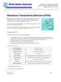
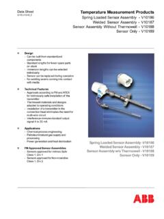
1 Address: Box 461947 Garland, TX 75046. Phone: 972-494-1566 Toll Free: 1-800-889-5478. Website: A Leading Manufacturer of Quality Thermocouple and RTD Assemblies Since 1972. Thermowells Thermowells are used to provide an isolation between a temperature sensor and the environment, either liquid, gas or slurry. A thermowell allows the temperature sensor to be removed and replaced without compromising either the ambient region or the process. Care must be taken in determining the material used for the thermowell as well as other Sensors offers design assistance that includes pressure, temperature and or corrosion as well as vibration effects of the fluids. This vibration can cause well stem failure. Thermo Sensors thermowell materials include: Carbon Steel 304 & 316 Stainless Steel Monel Brass Please refer to our order guide to assist in determining your needs.
2 We can also provide technical design assistance and application suggestions. Give us a call. How to Select Thermowells Introduction Thermowells are used to shield thermocouple elements against mechanical damage and corrosion. Many variations are available in a variety of materials to meet individual job specifications. The chemical and physical properties of all standard bar stock materials are rigidly controlled. All bar stock wells are drilled by the gun drilling process. Use of specially designed and constructed measuring equipment enables standard guaranteed bore concentricity to be within 10% of wall thickness. Internal threads are within 1/2 turn of standard plug gauge. External threads are within 1/4 turn of standard ring gauge. If required by purchase order, your Thermowells undergo an internal hydrostatic test as a final precaution against pressure failure.
3 Test pressures and duration are determined by the customer. Radiograph and other tests can be performed and results furnished upon request. A variety of alloys suitable for every thermowell requirement is available. thermowell material should be selected for ability to withstand the process environments, high thermal conductivity and low porosity to gases. Choosing Bore Sizes for Maximum Flexibility Where several types of temperature measuring instruments are used, the selection of a standard bore diameter can provide greater efficiency and flexibility of use. The same well can accommodate either thermocouple, resistance thermometer, bi- metal thermometer or test thermometer. The bore sizes of wells shown on this website accommodate the most commonly used temperature sensing elements. For example.
4 260 Diameter Bore: Thermo Sensors Corporation Copyright 2012. Page | 1. Address: Box 461947 Garland, TX 75046. Phone: 972-494-1566 Toll Free: 1-800-889-5478. Website: A Leading Manufacturer of Quality Thermocouple and RTD Assemblies Since 1972. Bi-Metal Thermometers (1/4" stem). Thermocouples (#14 Awg). 1/4" & 3/8" Cerampak Thermocouples & RTD's Liquid-in-glass Test Thermometers (unarmored). Other elements having .252 max..385 Diameter Bore: Bi-metal Thermometers (3/8" stem). Thermocouples (#14 Gauge). 1/4" & 3/8" Cerampak Thermocouples & 3/8" RTD's (Use .260 Bore for 1/4" RTD's). Liquid-in-glass Test Thermometers (armored). Other elements having .377 max. When to Use Tapered or Straight Thermowells Tapered Thermowells provide greater strength without sacrificing sensitivity. Because of its higher strength-to-weight ratio, the tapered thermowell provides greater resistance to high frequency vibrations than straight Thermowells .
5 This permits reliable operation at high fluid velocities. Thus, for higher fluid velocities, the tapered well should be chosen; for lower fluid velocities, the straight well. When choosing wells, refer to the velocity rating charts and other design information. Choosing the Material A most important factor in selecting thermowell material is to determine the corrosive conditions to which the well will be exposed. Recommended materials for various services are given in the thermowell Material Guide. The high mirror polish given to all wells enhances its corrosion resistance capability. Occasionally, the material consideration is one of strength rather than corrosion. For example, a stainless steel well may be required for high pressure water service, where a brass well might have been satisfactory from a corrosion viewpoint.
6 It will be helpful to consult the pressure-temperature ratings given for each well type. Choosing the Proper Connection In this website you will find standardized wells of threaded, flanged (ASA and Van Stone), and socket weld types with standard bore sizes. A provision for customer specifying design parameters or "weld-in" Thermowells is also provided. Threaded wells are made in readily weldable material. Standard flanged wells (other than Van Stone) have flanges welded front and back with "V" or "J" groove design. Full penetration double welded flanges are also available. The double-welded construction eliminates possible crevice corrosion and stress cracking. Heat treated to NACE specs is available. Socket weld of wells are especially simple to install. They fit ASA standard socket weld couplings or flanges to produce a clean, tight installation.
7 Thermo Sensors Corporation Copyright 2012. Page | 2. Address: Box 461947 Garland, TX 75046. Phone: 972-494-1566 Toll Free: 1-800-889-5478. Website: A Leading Manufacturer of Quality Thermocouple and RTD Assemblies Since 1972. Velocity Ratings of Thermowells In some cases, well failures are due, not to the effect of pressure, temperature, or corrosion, but to the vibrational effects to which they are subjected. Fluid, flowing by the well, forms a turbulent wake (the Von Karman Trail) with a definite frequency based on well dimensions and fluid velocity. If the natural frequency of the well equals the wake frequency, the well stem will vibrate to destruction and break off in the piping. It is, therefore, important that the well have sufficient design to prevent a frequency equality condition.
8 In the following tables, a recommended maximum velocity rating can be found for several standard well lengths and materials. To simplify the information, ratings given are based on operating temperatures of 1000 F. for wells made of Carbon Steel (C-1018) and Stainless Steel (304 and 316). Values for brass wells are based on 350 F. Operation limits for Monel wells are based on 900 F service. Slightly higher velocity is possible at lower temperatures. Single values appearing in the velocity tables may be considered safe for water, steam, air or gas. In shorter insertion lengths, consideration is given to the velocity pressure effect of water flowing at higher velocities. The values in parenthesis, therefore, represent safe values for water flow while the unbracketted value may be used for steam, air, gas and similar density fluids.
9 Maximum Fluid Velocity Feet per Second Well Type Material Insertion Length -"U". 2 4 7 10 13 16 22. 1V & 3V Carbon Steel 404 184 1G & 3G (129) ( ) ( ). and 304 & 316 SS 430 192 1F (179) ( ) ( ). Monel 350 168 61 (143) ( ) ( ). 2V & 4V Carbon Steel 410 248 2G & 4G (152) ( ) ( ). and 304 & 316 SS 444 285 2F (211) (117) ( ). Monel 338 226 (168) ( ) ( ). Maximum Fluid Velocity Feet per Second Well Type Material Insertion Length -"U". 2 1/2 4 1/2 7 1/2 10 1/2 13 1/2 16 1/2 19 1/2 22 1/2. 1A Brass 207 and ( ) ( ) ( ). 1B Carbon Steel 290 123 (106) ( ) ( ). 304 & 316 SS 300 128 (148) ( ). Monel 261 112 (118) ( ). 3A Brass 207 102 and ( ) ( ) (28). 3B Carbon Steel 290 143 Thermo Sensors Corporation Copyright 2012. Page | 3. Address: Box 461947 Garland, TX 75046. Phone: 972-494-1566 Toll Free: 1-800-889-5478.
10 Website: A Leading Manufacturer of Quality Thermocouple and RTD Assemblies Since 1972. (106) ( ) ( ). 304 & 316 SS 300 148 (148) (117). Monel 261 128 (118) ( ). Maximum Fluid Velocity Feet per Second Well Type Material Insertion Length -"U". 2 1/2 4 1/2 7 1/2 10 1/2 13 1/2 16 1/2 22 1/2. 1S Carbon Steel 290 123 (106) ( ) ( ). 304 & 316 SS 300 128 (148) ( ). 3S Carbon Steel 290 143 (106) ( ) ( ). 304 & 316 SS 300 148 (148) (117). 2S Carbon Steel 426 192 and (260) (144). 4S 304 & 316 SS 449 199 (360). Maximum Fluid Velocity Feet per Second Well Type Material Insertion Length -"U". 2 1/2 4 1/2 7 1/2 10 1/2 13 1/2 16 1/2 19 1/2 22 1/2. 1C Brass 305 and ( ) ( ). 1D Carbon Steel 386 180 (175) ( ) ( ). 304 & 316 SS 440 197 (243) (135). Monel 354 155 (195) (108). 3C Brass 354 108 and (161) ( ). 3D Carbon Steel 448 209 (289) (161).