Transcription of Thevenin / Norton equivalent circuits - Iowa State University
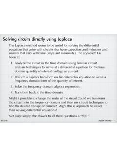
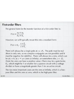
1 Thevenin / Norton equivalent circuits +. We have seen many instances where we can VS1. same +. take elements in a part of a circuit and VS1+VS2. combine them in some fashion to make an + . VS2. equivalent circuit . With respect to the two . terminals, the two versions behave identically. Anything attaching to the two terminals will not be able to tell the difference. +. VS = 0 IS = 0. same . IS1 IS2 IS1+IS2. short circuit open circuit R1 R. same + same R3 R4 Req VS IS R.. R2. Req = R1 + R2 + R3 R4 VS = IS R. G. Tuttle Thevenin / Norton 1. We can generalize this idea of equivalency by saying that any linear circuit that has a connection de ned by two nodes a port can be simpli ed to an equivalent circuit consisting of a voltage source and a resistor in series.
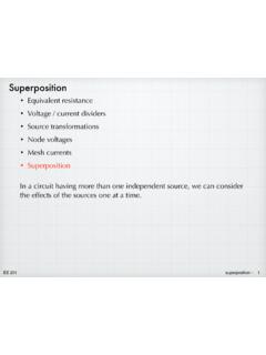
2 This remarkable result was proven by French engineer Leon Thevenin in 1883, and so we call the simpli ed voltage-source /. resistor combination the Thevenin equivalent . Terminology: A port is de ned by two nodes in a circuit . In principle, the port could be any random pair of nodes, but usually the port represents a place where we intend to connect another circuit . Common examples are the ubiquitous stereo audio jack and the even more ubiquitous USB plug. (Actually, both examples have multiple ports in a single package, but never mind that for now.). RTh a a Linear circuit with same!! VTh +. port a-b . b b This view that every linear circuit has an effective voltage (which could be zero!)
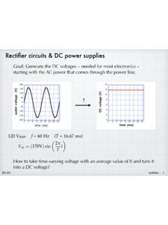
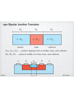
3 And an effective resistance completely changes the way that G. Tuttle we look at circuits . Thevenin / Norton 2. fi fi fi fi If we consider the output port of some audio generating gizmo a phone or whatever and want to hear the sound, we must connect a speaker of some sort headphones or a loudspeaker on the shelf. If we look at the circuitry that generates the audio signal, it appears rather bewildering to a novice. Yet, Thevenin says that all of that complication can be boiled down to two components. And the speaker itself has a Thevenin equivalent , which is just a single resistor, since the speaker does not generate a voltage on its own. Ra Va + Rsp . audio source speaker speaker Ra Va + Rsp.
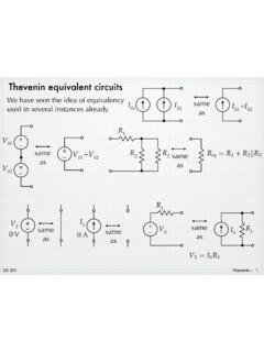
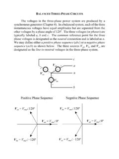
4 Audio circuit music!! G. Tuttle Thevenin / Norton 3. Norton equivalent Sometime later (c. 1926), a similar equivalency idea was put forth by Edward Norton working at Bell Labs. His idea was nearly identical to Thevenin 's, but Norton used a parallel combination of current source and resistor, rather than Thevenin 's series arrangement. (Apparently Norton was not aware of Thevenin 's earlier proof.). a a Linear circuit with same!! IN RN. port a-b b b Having seen source transformations earlier, this is not surprising to us . Norton is simply the source transformation of Thevenin . And vice-versa. We might recall that we never actually proved that source transformations were valid.
5 We inferred that they were equivalent using examples. G. Tuttle Thevenin / Norton 4. Using Thevenin and Norton , we have proof of the validity of source transformations. If Thevenin 's voltage- a source/resistor series combination is Linear equivalent to the original circuit , and circuit with Norton 's current-source/resistor port a-b b parallel combination is equivalent to the original circuit , then the two must also be equivalent to each other. RTh a a VTh = InRn VTh + IN RN.. RTh = Rn b b Thevenin Norton Some texts make a big deal about differentiating between Thevenin and Norton . We will take the view that they are simply two manifestations of the same idea.
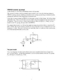
6 As soon as we know one equivalent circuit , we immediately know the other through source transformation, and in any particular case, we use the version that is most suitable to the problem. G. Tuttle Thevenin / Norton 5. To further illustrate the equivalence idea, consider the circuit shown below basically, it is the familiar two-source, two-resistor circuit with a port de ned by the two nodes a and b. Attach various load resistors to the port, and calculate the resulting voltage across the load along with the current and power. The results are given in the table. R1. a RL vRL iRL PRL. 10 k . VS + IS R2 50 V mA mW.. 10V 4 mA 10 k . b 500 V mA mW. R1. iRL. + 5 k V mA mW.
7 VS + IS R2 vRL RL. 50 k V mA mW.. 500 k V A mW. G. Tuttle Thevenin / Norton 6. fi Now consider the simple source and resistor circuit shown below. Attach the same load resistors and calculate the resulting voltages, currents, and powers. The results are shown in the table. The results from this simple circuit are identical to those from the circuit on the previous page. In terms of a load that is attached at the port, the two circuits are indistinguishable. We can use the equivalent in place of the original and have identical results. This is the idea that was proven by Thevenin . RTh a RL vRL iRL PRL. 5 k . VTh + 50 V mA mW.. 25 V. b 500 V mA mW. RTh iRL 5 k V mA mW.
8 +. VTh + vRL RL 50 k V mA mW.. 500 k V A mW. G. Tuttle Thevenin / Norton 7. Determining the Thevenin / Norton values Now comes a crucial question: Given a black box circuit , how do we determine VTh and RTh? (Or IN and RN ?). Since there are two components in an equivalent circuit , we will need to do two measurements (if working in the lab) or two calculations (if working with pencil and paper) and then determine the Thevenin or Norton values from those results. There is no easy way out there must be two independent measurements/calculations. Fortunately, we have already learned the analysis and lab skills needed. We use the Thevenin equivalent as a guide in determining the process.
9 The technique involves nothing more than attaching two different loads to the port and then measuring or calculating the resulting voltages or currents at the port. We will illustrate the idea using random values for the two loads. Then we will sharpen the technique by having the port be open circuited and then short circuited. First consider what happens with a simple source + resistor circuit in which we don't know the values of the source or the resistor. G. Tuttle Thevenin / Norton 8. 1. Attach a load resistor, RL1. 2. Attach another, different load Measure resulting v1. resistor, RL2. Measure resulting v2. RTh RTh + +. VTh + v1 R1 VTh + v2 RL2.. RL1 RL2.
10 V1 = VTh v2 = VTh RL1 + RTh RL2 + RTh Knowing v1 and v2, it is a simple matter to use the two equations to solve for the two unknowns, VTh and RTh. We could also use the same approach with a Norton equivalent : i1 i2. IN RN RL1 IN RN RL2. 1. 1. RL2. i1 =. RL1. I i2 = 1 1. IN. 1. + 1 N. RL2. + RN. G. Tuttle RL1 RN Thevenin / Norton 9. Now that we see the basic approach, we can apply it to other circuits . Attach a known load resistance and determine the corresponding port voltage. Then attach a second load and nd the port voltage for that. Use the results to nd the Thevenin (or Norton ) equivalent for the circuit . i1. Linear + RL1 v1v2 (RL1 RL2). circuit with RL1 v1 = VTh VTh =.