Transcription of Thick Film Chip Resistors 01005, 0201, 0402, 0603, 0805 ...
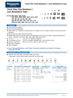
1 Thick film chip Resistors Thick film chip Resistors 01005, 0201, 0402, 0603, 0805, 1206, 1210, 1812, 2010 , 2512. Type: ERJ XG, 1G, 2G, 3G, 6G, 8G, 14, 12, 12Z, 1T. Features Small size and lightweight High reliability Metal glaze Thick film resistive element and three layers of electrodes Compatible with placement machines Taping packaging available Suitable for both reflow and flow soldering Reference Standards IEC 60115-8, JIS C 5201-8, EIAJ RC-2134B. Explanation of Part Numbers ERJXGN, 1GE, 2GE, 3GE, 6GE, 8GE, 14, 12, 12Z, 1T Series, 5 % type 1 2 3 4 5 6 7 8 9 10 11 12. E R J 3 G E Y J 1 0 2 V. Size, Power Rating Marking Resistance Tolerance Packaging Methods Product Code Thick film Type : inches Power R. Code Marking Code Tolerance Code Packaging Type chip Resistors XGN : 01005 W Value Marking on J 5 % Pressed Carrier Taping Y Y ERJXGN. black side 2 mm pitch, 20000 pcs. 1GE : 0201 W 0 Jumper 2GE : 0402 W Nil No marking Pressed Carrier Taping C ERJ1GE.
2 2 mm pitch, 15000 pcs. 3GE : 0603 W. 6GE : 0805 W Resistance Value Punched Carrier Taping X ERJ2GE. 2 mm pitch, 10000 pcs. 8GE : 1206 W The first two digits are significant figures of resistance and 14 : 1210 W ERJ3GE. the third one denotes number of zeros following. Punched Carrier Taping 12 : 1812 W Decimal Point is expressed by R as = 4R7. V ERJ6GE. 4 mm pitch 12Z : 2010 W Jumper is expressed by R00. ERJ8GE. 1T : 2512 1W ERJ14. Embossed CarrierTaping ERJ12. U. 4 mm pitch ERJ12Z. When omitted, the rest of the P/N factors shall be moved up respectively. ERJ1T. (Only XGN, 1GN, 2GE type). Design and specifications are each subject to change without notice. Ask factory for the current technical specifications before purchase and/or use. Should a safety concern arise regarding this product, please be sure to contact us immediately. Jul. 2008. Thick film chip Resistors Construction Dimensions in mm (not to scale).
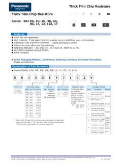
3 L. a W. Protective coating Electrode (Inner) t Alumina substrate b Type Dimensions (mm) Mass (Weight). (inches) L W a b t (g/1000 pcs.). ERJXG (01005). ERJ1G Electrode (0201). (Between) ERJ2G. (0402) ERJ3G + 2. (0603) ERJ6G 4. (0805). ERJ8G + + 10. (1206) ERJ14 16. Thick film (1210). resistive element Electrode (Outer). ERJ12 27. (1812). ERJ12Z 27. ( 2010 ). ERJ1T 45. (2512). Ratings <For resistor >. Limiting Element Maximum Overload Resistance Resistance Category Temperature Type Power Rating (2) Range (Operating Voltage (Maximum Voltage Tolerance Range [ 10 6 / C Temperature Range). (inches) at 70 C (W) (1). RCWV) (V) (V) (%) ( ) (ppm/ C)] ( C). <10 : 100 to +600. ERJXG 15 30 5 to 1 M (E24) 10 to 100 : 300 55 to +125. (01005). 100 < : 200. ERJ1G 25 50 5 1 to 10 M (E24) 55 to +125. (0201). ERJ2G <10 : (0402) 50 100 5 1 to 10 M (E24) 100 to +600 55 to +155. ERJ3G 75 150 5 1 to 10 M (E24) 55 to +155. (0603). ERJ6G 150 200 5 1 to 10 M (E24) 55 to +155.
4 (0805). ERJ8G 10 to 1 M : (1206) 200 400 5 1 to 10 M (E24) 200 55 to +155. ERJ14 200 400 5 1 to 10 M (E24) 55 to +155. (1210). ERJ12 200 500 5 1 to 10 M (E24) 55 to +155. (1812). ERJ12Z. ( 2010 ) 200 500 5 1 to 10 M (E24) 1 M <: 55 to +155. 400 to +150. ERJ1T 1 200 500 5 1 to 1 M (E24) 55 to +155. (2512). (1) Rated Continuous Working Voltage (RCWV) shall be determined from RCWV= Power Rating Resistance Values, or Limiting Element Voltage (max. RCWV) listed above, whichever less. (2) Overload (Short-time Overload) Test Voltage (SOTV) shall be determined from SOTV= Power Rating or max. Overload Voltage listed above whichever less. <For Jumper> Power Derating Curve Type Rated Current Maximum Overload Current For Resistors operated in ambient temperatures above (inches) (A) (A). 70 C, power rating shall be derated in accordance ERJXG (01005). 1 with the figure below. ERJ1G (0201). ERJ2G (0402) 55 C 70 C. 1 2 100. ERJ3G (0603).
5 Rated Load (%). 2G, 3G, 6G, 8G, ERJ6G (0805) 80 14, 12, 12Z, 1T. ERJ8G (1206) 60. ERJ14 (1210) 40. 2 4 20. XG, 1G 155 C. ERJ12 (1812) 125 C. ERJ12Z ( 2010 ) 0. 60 40 20 0 20 40 60 80 100 120 140 160 180. ERJ1T (2512) Ambient Temperature ( C). Design and specifications are each subject to change without notice. Ask factory for the current technical specifications before purchase and/or use. Should a safety concern arise regarding this product, please be sure to contact us immediately. Jul. 2008. Thick film chip Resistors Packaging Methods (Taping). Standard Quantity Type Kind of Taping Pitch (P1) Quantity ERJXG 20000 Pressed Carrier Taping ERJ1G 2 mm 15000 ERJ2G 10000 ERJ3G. Punched Carrier Taping ERJ6G. ERJ8G. 5000 ERJ14 4 mm ERJ12. Embossed Carrier Taping ERJ12Z. ERJ1T 4000 Carrier Tape (Unit : mm). Pressed Carrier Punched Carrier Embossed Carrier P1 P2 P0. D0. E. F. W. B. T T T A P1 (2 mm pitch). D1 (Only Emboss).
6 Type A B W F E P1 P2 P0 D0 T D1. ERJXG . ERJ1G . ERJ2G . ERJ3G . ERJ6G . + 0 ERJ8G . ERJ14 + 0. ERJ12 ERJ12Z min. ERJ1T Taping Reel (Unit : mm). Type A B C W T. T ERJXG. ERJ1G. C. ERJ2G. ERJ3G B. ERJ6G. +0. 60 min. ERJ8G. ERJ14. ERJ12. A W ERJ12Z ERJ1T. Design and specifications are each subject to change without notice. Ask factory for the current technical specifications before purchase and/or use. Should a safety concern arise regarding this product, please be sure to contact us immediately. Feb. 2006. Thick film chip Resistors Recommended Land Pattern In case of flow soldering, the land width must be smaller than the chip resistor width to control the solder amount properly. Generally, the land width should be to times (W) of the width of chip resistor . In case of reflow soldering, solder amount can be adjusted, therefore the land width should be set to to times chip resistor width (W). Type Dimensions (mm).
7 chip resistor (inches) a b c ERJXG (01005) to to to ERJ1G (0201) to to to ERJ2G (0402) to to to c ERJ3G (0603) to 2 to to 1. ERJ6G (0805) 1 to to to a ERJ8G (1206) 2 to to 5 to ERJ14(1210) 2 to to 5 to b ERJ12(1812) to to to ERJ12Z( 2010 ) to 4 to 7 to ERJ1T(2512) 5 to to to Recommended Soldering Conditions Recommendations and precautions are described below. Recommended soldering conditions for reflow Reflow soldering shall be performed a maximum of two times. Please contact us for additional information when used in conditions other than those specified. For soldering (Example : Sn/Pb). Please measure the temperature of the terminals Temperature Time and study every kind of solder and printed circuit Preheating 140 C to 160 C 60 s to 120 s board for solderability before actual use. Main heating Above 200 C 30 s to 40 s Peak Peak 235 5 C max. 10 s Temperature Preheating For lead-free soldering (Example : Sn/Ag/Cu).
8 Temperature Time Heating Preheating 150 C to 180 C 60 s to 120 s Main heating Above 230 C 30 s to 40 s Peak max. 260 C max. 10 s Time Recommended soldering conditions for flow For soldering For lead-free soldering Temperature Time Temperature Time Preheating 140 C to 180 C 60 s to 120 s 150 C to 180 C 60 s to 120 s Soldering 245 5 C 20 s to 30 s max. 260 C max. 10 s Safety Precautions The following are precautions for individual products. Please also refer to the precautions common to Fixed Resistors shown on page ER2 of this catalog. 1. Take measures against mechanical stress during and after mounting of Thick film chip Resistors (hereafter called the Resistors ) so as not to damage their electrodes and protective coatings. 2. If a transient load (heavy load in a short time) like a pulse is expected to be applied, check and evaluate the operations of the Resistors when installed in your products before use. Never exceed the rated power.
9 Otherwise, the performance and/or reliability of the Resistors may be impaired. 3. Do not use halogen-based or other high-activity flux. Otherwise, the residue may impair the Resistors ' performance and/or reliability. 4. When soldering with a soldering iron, never touch the Resistors ' bodies with the tip of the soldering iron. When using a soldering iron with a high temperature tip, finish soldering as quickly as possible (within three seconds at 350 C max.). 5. As the amount of applied solder becomes larger, the mechanical stress applied to the Resistors increases, causing problems such as cracks and faulty characteristics. Avoid applying an excessive amount of solder. 6. Do not apply shock to the Resistors or pinch them with a hard tool ( pliers and tweezers). Otherwise, the Resistors '. protective coatings and bodies may be chipped, affecting their performance. 7. Avoid excessive bending of printed circuit boards in order to protect the Resistors from abnormal stress.
10 Design and specifications are each subject to change without notice. Ask factory for the current technical specifications before purchase and/or use. Should a safety concern arise regarding this product, please be sure to contact us immediately. Feb. 2006. Safety Precautions (Common precautions for Fixed Resistors ). When using our products, no matter what sort of equipment they might be used for, be sure to make a written agreement on the specifi cations with us in advance. The design and specifi cations in this catalog are subject to change without prior notice. Do not use the products beyond the specifications described in this catalog. This catalog explains the quality and performance of the products as individual components. Before use, check and evaluate their operations when installed in your products. Install the following systems for a failsafe design to ensure safety if these products are to be used in equipment where a defect in these products may cause the loss of human life or other significant damage, such as damage to vehicles (au to mo bile, train, vessel), traffi c lights, medical equipment, aerospace equipment, elec tric heating appliances, combustion/gas equipment, rotating equipment, and disaster/crime prevention equipment.