Transcription of Thick Film Chip Resistors - Farnell element14
1 Thick film chip Resistors Description: The Resistors are constructed in a high grade ceramic body (aluminum oxide). Internal metal electrodes are added at each end and connected by a resistive paste that is applied to the top surface of the substrate. The composition of the paste is adjusted to give the approximate resistance required and the value is trimmed to within tolerance by laser cutting of this resistive layer. The resistive layer is covered with a protective coat. Finally, the two external end terminations are added. For ease of soldering the outer layer of these end terminations is a Tin (lead free) alloy. Features: high reliability and stability Reduced size of final equipment Lower assembly costs Higher component and equipment reliability Application: Consumer electrical equipment EDP, Computer application Quick Reference Data Telecom application Item General Specification Series No.
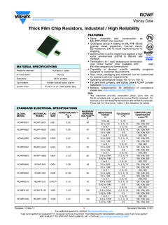
2 MCWR12 MCWR08 MCWR06 MCWR04. Size code 1206(3216) 0805(2012) 0603(1608) 0402(1005). Resistance Range 1 to10M 1% tolerance 1%. Resistance Tolerance E96/E24. TCR (ppm/ C). 100. 10M R >10. -200 to +400. R 10 . Max. dissipation 1/4 W 1/8 W 1/10 W 1/16 W. @ Tamb=70 C. Max. Operation 200V 150V 75V 50V. Voltage (DC or RMS). Max. Overload 400V 300V 150V 100V. Voltage (DC or RMS). Climatic category 55/155/56. Note : 1. Max. Operation Voltage : So called RCWV (Rated Continuous Working Voltage) is determined by RCWV = Rated Power Resistance Value or Max. RCWV listed above, whichever is lower. 2. The resistance of Jumper is defined < . Page <1> 05/12/17 Thick film chip Resistors MCWR12 MCWR08 MCWR06 MCWR04.
3 L 2 1 W T Tb Tt Dimensions : Millimetres Functional Description: Product characterization Standard values of nominal resistance is E96 series for Resistors with a tolerance of 1%. Derating The power that the resistor can dissipate depends on the operating temperature; see Figure 2 Maximum dissipation in percentage of rated power as a function of the ambient temperature for MCWR12, MCWR08, MCWR06, MCWR04. Mounting Due to their rectangular shapes and small tolerances, Surface Mountable Resistors are suitable for handling by automatic placement systems. chip placement can be on ceramic substrates and printed-circuit boards (PCBs). Electrical connection to the circuit is by individual soldering condition.
4 The end terminations guarantee a reliable contact. Page <2> 05/12/17 Thick film chip Resistors Soldering Condition: The robust construction of chip Resistors allows them to be completely immersed in a solder bath of 260 C for 10 seconds. Therefore, it is possible to mount Surface Mount Resistors on one side of a PCB and other discrete components on the reverse (mixed PCBs). Surface Mount Resistors are tested for solderability at 235 C during 2 seconds. The test condition for no leaching is 260 C for 30 seconds. Typical examples of soldering processes that provide reliable joints without any damage are given in Fig 3. 260. 245 max. ramp up rate = 3 C/s max. ramp down rate = 6 C/s 217.
5 200. Temp. (DegC). 150. For SnAgCu series solder pase 25. 30 sec min Time 60 120 Sec 60 150 Sec 480 Sec max to Peak Fig 3. Infrared soldering profile for chip Resistors Catalogue Numbers: The Resistors have a catalogue number starting with MCWR12 X 472_ J T L. Size code Type code Resistance code Tolerance Packaging code Termination MCWR12 : 1206 X: 5%, E24: 2 significant F : 1% T : 7" Reeled taping code MCWR08 : 0805 1%, 10 to 1M digits followed by no. of P : Jumper Q : 10" Reeled taping L = Sn base zeros and a blank (lead free). MCWR06 : 0603 W: G : 13" Reeled taping =4R7_. MCWR04: 0402 1%, < 10 ; >1M H : 13" reel 50 Kpcs 10 =100_ only for 0402. 220 =221_ B : Bulk Jumper =000_ D : 7" reel 20 Kpcs ("_" means a blank) only for 0402.
6 1%, E24+E96: 3 significant A : 7" reel 15 Kpcs digits followed by no. of only for 0402. zeros 102 =1020. =3742. MCWR12, MCWR08, MCWR06: 1. Reeled tape packaging : 8mm width paper taping 5,000pcs per 7" reel, 10kpcs per 10" reel, 20kpcs per 13" reel. 2. Bulk packaging : 5,000pcs per poly-bag MCWR04: 1. Reeled tape packaging : 8mm width paper taping 10,000pcs per 7" reel, 20,000pcs per 10" reel. 70,000pcs per 13" reel. 2. Bulk packaging : 10,000pcs per poly-bag Page <3> 05/12/17 Thick film chip Resistors Test and Requirements: Essentially all tests are carried out according to the schedule of IEC publication 115-8, category LCT/UCT/56 (rated temperature range : Lower Category Temperature, Upper Category Temperature; damp heat, long term, 56 days).
7 The testing also meets the requirements specified by EIA, EIAJ and JIS. The tests are carried out in accordance with IEC publication 68, "Recommended basic climatic and mechanical robustness testing procedure for electronic components" and under standard atmospheric conditions according to IEC 60068-1, subclause Unless otherwise specified, the following value supplied : Temperature: 15 C to 35 C. Relative humidity: 45% to 75%. Air pressure: 86kPa to 106 kPa (860 mbar to 1060 mbar). All soldering tests are performed with midly activated flux. Requirement Test Procedure / Test Method resistor 0 . - DC resistance values measurement - Temperature Coefficient of Resistance ( ). Electrical Natural resistance change per change in degree centigrade.
8 Within the specified Characteristics tolerance Refer to JISC5201-1: 1998 t1 : 20 C+5 C/-1 C; t2 : -55 C or +155 C "QUICK REFERENCE <50m . Clause DATA". R1 : Resistance at reference temperature (20 C +5 C / -1 C). R2 : Resistance at test temperature (-55 C or +155 C). Resistance to 1%: R/Rmax. soldering heat( ) Un-mounted chips completely immersed for 10 1second in a ( + ) <50m . JISC5201-1:1998 SAC solder bath at 260 C 5 C. no visible damage Clause Solderability Un-mounted chips completely immersed for 10 1second in a 95% coverage min., good JISC5201-1: 1998 SAC. tinning and no visible damage Clause solder bath at 235 C 5 C. 30 minutes at -55 C 3 C, 2-3 minutes at 20 C +5 C -1 C, Temperature cycling 1%: R/Rmax.
9 30 minutes at JISC5201-1: 1998 ( + ) <50m . +155 C 3 C, 2-3 minutes at 20 C +5 C -1 C, total 5 continuous Clause No visible damage cycles high Temperature 1%: R/. Exposure 1,000 +48/-0 hours; without load in a temperature chamber Rmax. (1%+ ) <50m . MIL-STD-202 controlled 155 3 C. No visible damage method 108. Bending strength 1%: R/. Resistors mounted on a 90mm glass epoxy resin PCB(FR4), JISC5201-1: 1998 Rmax. (1%+ ) <50m . bending once 3mm for 10sec, 5mm for MCWR04. Clause No visual damaged Adhesion No remarkable damage or JISC5201-1: 1998 Pressurizing force: 5N, Test time: 10 1sec. removal of the terminations Clause Short Time Overload 1%: R/R max. (STOL). times RCWV or max.
10 Overload voltage, for 5seconds (1%+ ) <50m . JISC5201-1: 1998. No visible damage Clause Page <4> 05/12/17 Thick film chip Resistors Requirement Test Procedure / Test Method resistor 0 . Load life in Humidity 1000 +48/-0 hours, loaded with RCWV or Vmax in humidity 1%: R/R max. JISC5201-1: 1998 chamber controller at 40 C 2 C and 90 to 95% relative humidity, (1%+ ) <50m . Clause on and hours off No visible damage Load life (endurance) 1%: R/R max. 1000 +48/-0 hours, loaded with RCWV or Vmax in chamber JISC5201-1: 1998 (1%+ ) <50m . controller 70 2 C, hours on and hours off Clause No visible damage Insulation Resistance JISC5201-1: 1998 Apply the maximum overload voltage (DC) for 1minute R 10G.