Transcription of THREAD GAGING REFERENCE GUIDE
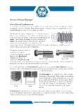
1 Know your threads, L. S. STARRETT COMPANY121 Crescent Street Athol, MA 01331 Telephone (508) 249-3551 Fax (508) 249-8495 Table of ContentsSECTION 1:Fundamentals of Screw THREAD Technology .. 4 - 7 SECTION 2:Definitions and Terminology .. 8 - 11 SECTION 3:Gage Design Contacts .. 12 - 13 SECTION 4:Technical Considerations .. 14 - 23 SECTION 5:Plating, Metric and RFQ .. 24 - 274 Screw THREAD DesignationScrew THREAD DesignationScrew THREAD DesignationScrew THREAD DesignationScrew THREAD DesignationEXAMPLE: .3125 - 24 UNJF - 3A (B).3125 = Nominal Diameter = Maximum Major Diameter24= Number of threads per inchUN= Unified National (60 V- THREAD )J= Controlled root radius High Strength(Minor diameter increased from UN to UNJ.)F= Fine THREAD series3= THREAD classA= External threadB= Internal threadScrew THREAD AssemblyFUNDAMENTALS OF SCREW THREAD TECHNOLOGY5 SECTION 1 Functional Diameter SizeWidth of THREAD Ridge = Width of THREAD GroovePitch Diameter Size + Variations of THREAD Elements and Characteristics = Functional Diameter SizePitch Diameter SizeThe Functional diametersize is the Pitch diam-eter size plus the cumu-lative effect of variationsin lead, (including unifor-mity of helix) flankangle, taper, and round-ness.
2 The Functionalsize is the measuredvalue of the maximummaterial size of either aproduct internal orexternal screw Pitch diameter sizeis defined as the diam-eter of a cylinder thatpasses through thethread profile of either aproduct internal orexternal screw THREAD tomake the widths ofthread ridge and threadgroove equal on bothsides of the THREAD . ThePitch diameter is themeasured value of theminimum material limitof size of either a prod-uct internal or externalscrew THREAD . FSPD ThreadFormVariation tssttsPD tsTHREAD RIDGE flflflflflTHREAD GROOVE flflflflfl =6 FUNDAMENTALS OF SCREW THREAD TECHNOLOGYR eference Federal Standard H28/20 Systems of Gagingttttt SYSTEM 21 SYSTEM 21 SYSTEM 21 SYSTEM 21 SYSTEM 21. GO/NO GO GAGING . GO/NO GO GAGING . GO/NO GO GAGING . GO/NO GO GAGING . GO/NO GO System 21 provides for interchangeable assembly withfunctional size control at the maximum material limits within the length of standard GAGING elements;and also control of character-istics identified as NOT-GO functional diameters or as HI (Internal)and LO (External) functional diameters.
3 These functional gages provide some control at the mini-mum material limit when there is little variation in THREAD form characteristics such as lead, flankangle, taper and SYSTEM 22 SYSTEM 22 SYSTEM 22 SYSTEM 22 SYSTEM 22. VARIABLES INDICATING TYPE GAGING . VARIABLES INDICATING TYPE GAGING . VARIABLES INDICATING TYPE GAGING . VARIABLES INDICATING TYPE GAGING . VARIABLES INDICATING TYPE System 22 provides for interchangeable assembly withfunctional size control at the maximum material limits within the length of standard GAGING elements;and also control of the minimum material size limits over the length of the full THREAD . Other threadcharacteristics such as lead, flank angle, taper and roundness variations are confined within theselimits with no specific control of their magnitudes. For UNJ and MJ external threads, control is alsoprovided for the THREAD root radius and rounded root minor SYSTEM 23.
4 SAFETY CRITICAL SAFETY CRITICAL SAFETY CRITICAL SAFETY CRITICAL SAFETY CRITICAL ttttt THREAD acceptability criteria are in accordance with Section 6 of ASME Alsosee subsection REFERENCE Standardsttttt ASME ASME ASME ASME ASME Unified Inch Screw ASME ASME ASME ASME ASME Gages and GAGING for Unified Inch Screw ASME ASME ASME ASME ASME Screw THREAD GAGING Systems for Dimensional Acceptability Inch and MetricThreads (UN, UNR, UNJ, M and MJ).7 THREAD - 20 UNC - Class?SECTION 1 Classes of threads are differentiated by the amount of tolerance andallowance specified. Indicating GAGING is typically mastered at maximummaterial condition. This is the minimum Pitch diameter tolerance limit threads and the maximum Pitch diameters tolerance limit for } 1 FIGURE 1 FIGURE 1 FIGURE 1 FIGURE 1 Screw ThreadScrew ThreadScrew ThreadScrew ThreadScrew ThreadThe Screw THREAD is a ridge, usually ofuniform section and produced by form-ing a groove as a helix on the externalor internal surface of a cylinder, or as aconical spiral on the external or internalsurface of a cone.
5 A screw threadformed on a cylinder is known as astraight or parallel THREAD , to distinguishit from a tapered THREAD that is formedon a 2 FIGURE 2 FIGURE 2 FIGURE 2 FIGURE 2 FIGURE 3 FIGURE 3 FIGURE 3 FIGURE 3 FIGURE 3 ThreadThreadThreadThreadThreadA THREAD is a portion of a screw threadencompassed by one ridge wrappedaround a cylinder or cone for one com-plete Start ThreadSingle Start ThreadSingle Start ThreadSingle Start ThreadSingle Start ThreadA single start THREAD is one having oneridge wrapped around a cylinder orcone for the total ThreadMultiple-Start ThreadMultiple-Start ThreadMultiple-Start ThreadMultiple-Start ThreadA multiple-start THREAD is one that hastwo or more ridges wrapped around acylinder or cone for the total ThreadExternal ThreadExternal ThreadExternal ThreadExternal ThreadAn external THREAD is on a cylindrical orconical external surface (referenceFigures 1, 2 and 3).DEFINITIONS AND TERMINOLOGY9 SECTION 2 FIGURE 4 FIGURE 4 FIGURE 4 FIGURE 4 FIGURE 4 FIGURE 7 FIGURE 7 FIGURE 7 FIGURE 7 FIGURE 7 Flank of ThreadFlank of ThreadFlank of ThreadFlank of ThreadFlank of ThreadThe flank (or side) of the ridge.
6 The flank surface inter-section with an axial plane is theoretically a of ThreadCrest of ThreadCrest of ThreadCrest of ThreadCrest of ThreadThe crest is that surface of the THREAD that joins theflank of the THREAD and is farthest from the cylinder orcone from which the THREAD of ThreadRoot of ThreadRoot of ThreadRoot of ThreadRoot of ThreadThe root is that surface of the THREAD that joins theflanks of adjacent THREAD forms and is identical with orimmediately next to the cylinder or cone from which thethread ThreadRight-Hand ThreadRight-Hand ThreadRight-Hand ThreadRight-Hand ThreadA THREAD is a right-hand THREAD if, whenviewed axially, it windsin a clockwise andreceding direction. Athread is consideredright-hand unlessspecifically ThreadLeft-Hand ThreadLeft-Hand ThreadLeft-Hand ThreadLeft-Hand ThreadA THREAD is a left-handthread if, when viewedaxially, it winds in acounterclockwise andreceding direction. Allleft-hand threads aredesignated ThreadInternal ThreadInternal ThreadInternal ThreadInternal ThreadAn internal THREAD is on a cylindrical orconical internal 5 FIGURE 5 FIGURE 5 FIGURE 5 FIGURE 5 FIGURE 6 FIGURE 6 FIGURE 6 FIGURE 6 FIGURE 610 DefinitionsDefinitionsDefinitionsDefinit ionsDefinitions &&&&& TerminologyTerminologyTerminologyTermino logyTerminologyDEFINITIONS AND TERMINOLOGYM aximum Material ConditionMaximum Material ConditionMaximum Material ConditionMaximum Material ConditionMaximum Material ConditionThe condition where the product screw THREAD contains the maximum amountof Material ConditionMinimum Material ConditionMinimum Material ConditionMinimum Material ConditionMinimum Material ConditionThe condition where the product screw THREAD contains the minimum amount total amount of variation permitted for the size of a dimension.
7 It is thedifference between the maximum limit of size and the minimum limit of size fora given THREAD difference between the design (maximum material) size and the basic SizeBasic SizeBasic SizeBasic SizeBasic SizeThe basic size is that size from which the limits of size are derived by theapplication of allowances and SizeDesign SizeDesign SizeDesign SizeDesign SizeThe design size is the basic size with allowance applied, from which the limitsof size are derived by the application of tolerance. If there is no allowance, thedesign size is the same as the basic SizeNominal SizeNominal SizeNominal SizeNominal SizeThe nominal size is the designation that is used for general identifical of seriesThread seriesThread seriesThread seriesThread seriesThread series are groups of diameters/pitch combinations distinguished fromeach other by the number of threads per inch applied to specific of ThreadClasses of ThreadClasses of ThreadClasses of ThreadClasses of ThreadClasses of threads are distinguished from each other by the amount of toler-ance or tolerance and allowance is not pitch diameter, threads per inch (TPI), nor is it LEAD, but it is theaxial distance defined in (x,y) between any point on a THREAD to the correspond-ing point on the adjacent of THREAD startsPitch =Number of threads per inchLeadLeadLeadLeadLeadLead is the axial advance per unit rotation for a given pitch distance.
8 Pitchequals lead when the THREAD form is CylinderMajor CylinderMajor CylinderMajor CylinderMajor CylinderThe major cylinder bounds the crest of an external straight THREAD or the root ofan internal straight CylinderMinor CylinderMinor CylinderMinor CylinderMinor CylinderThe minor cylinder bounds the root of an external straight THREAD or the crest ofan internal CylinderPitch CylinderPitch CylinderPitch CylinderPitch CylinderThe pitch cylinder is one of such diameter and location of its axis that its sur-face would pass through a straight THREAD in such a manner as to make thewidth of the THREAD ridge and the THREAD groove LinePitch LinePitch LinePitch LinePitch LineThe pitch line is linear and parallel to the center line of the pitch cylinder. De-fined where THREAD ridge and THREAD groove are equal along the length of AxisThread AxisThread AxisThread AxisThread AxisThe THREAD axis is the axis of its pitch SizeActual SizeActual SizeActual SizeActual SizeAn actual size is a measured 2 REFERENCE .
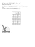
9 ASME &&&&& TerminologyTerminologyTerminologyTermino logyTerminology12 GAGE DESIGN CONTACTSUN GAGE PROFILE CONTACTSGage Contact Profile forPitch Diameter Size MeasurementsGage Contact Profile forGage Contact Profile forGage Contact Profile forGage Contact Profile forGage Contact Profile forFunctional Diameter Size MeasurementsFunctional Diameter Size MeasurementsFunctional Diameter Size MeasurementsFunctional Diameter Size MeasurementsFunctional Diameter Size MeasurementsFunctional ContactFunctional ContactProduct External Vee Cone ContactProduct External ThreadPITCH DIAMETER SIZEFUNCTIONAL DIAMETER SIZE13 INTERNAL UN GAGE PROFILE CONTACTSGage Contact Profile forGage Contact Profile forGage Contact Profile forGage Contact Profile forGage Contact Profile forFunctional Diameter Size MeasurementsFunctional Diameter Size MeasurementsFunctional Diameter Size MeasurementsFunctional Diameter Size MeasurementsFunctional Diameter Size MeasurementsGage Contact Profile forPitch Diameter Size Measurements14 SECTION 3 - TECHNICAL CONSIDERATIONSP roduct Screw THREAD Elements & CharacteristicsnLEADnLongnShortnIncludes helical deviation"drunk THREAD "nFLANK ANGLEnPlusnMinusnTAPERnFrontnBacknOUT OF ROUNDnEven lobenOdd lobenMAJOR DIAMETERnPITCH DIAMETERnMINOR DIAMETERINDICATING THREAD GAGINGGage Contact DesignsGage Contact DesignsGage Contact DesignsGage Contact DesignsGage Contact Designs Pitch Diameter Size Cone & Vee Rolls (120 ) Functional Diameter Size Multi-Rib Rolls (120 ) Functional Diameter Size Full Form Segments (180 )15 SECTION 4nH = Height of the Fundamental Triangle: (Cos 30 / TPI) or (Cos 30 x P)nFLANK ANGLES are made up of the two half angles of 30 each forthe 60 included DIAMETER is at P/8 or DIAMETER is at P/2 or DIAMETER is at P/4 or for UN or UNJ is at 5P/16 or.
10 3125 PnTPI = Number of Threads per InchnN = Number of THREAD StartsnP = PitchP = N/TPIA natomy of a UN or UNJ Screw ThreadUNJ LeadTECHNICAL CONSIDERATIONSI dealLead LongLead ShortLead Lead is the axial advance per unit rotation for a given pitch distance. P 17A virtual variation in effective diameter also occurs if the flankangle deviates from its specified 4 VARIATIONS Flank AngleFIGURE Variation ofEffective Diameter dueto Errors in Flank : Sidders; GUIDE to World Screw Threads, page 212, Figure GAGING TaperTECHNICAL CONSIDERATIONSTo measure Taper:Use the Pitch diameter gage (cone and vee) and measure atpositions along the length of THREAD without rotating the deviation of the dial indicator needle will tell the directionand magnitude of the tapered External Vee Cone Contact 1234567890123456789012345678901234567890 1123456789011234567890112345678901234567 8901234567890123456789011234567890112345 6789011234567890112345678901123456789011 23456789011234567890112345678901fi fi 19 SECTION 4 DIFFERENTIAL GAGING Out-of-RoundTo measure Out-of-Round:Use the 180 Functional segment to capture the full magni-tude of an egg-shaped (even lobe) out-of-round.