Transcription of Throttle & Choke Control Installation & Adjustment Guide
1 Throttle &. Choke Control Installation &. Adjustment Guide Contents Page No. Safety Precautions .. 2-3. Magnum Twin Horizontal Shaft .. 4-7. Magnum Twin Vertical Shaft .. 8-10. Command Single Cylinder .. 11-15. Command Twin Cylinder .. 16-19. OHC Twin Cylinder .. 20-23. 1. Safety Precautions To insure safe operations please read the following statements and understand their meaning. Also refer to your equipment owner's manual for other important safety information. This manual contains safety precautions which are explained below. Please read carefully. WARNING. Warning is used to indicate the presence of a hazard that can cause severe personal injury, death, or substantial property damage if the warning is ignored.
2 CAUTION. Caution is used to indicate the presence of a hazard that will or can cause minor personal injury or property damage if the warning is ignored. NOTE. Note is used to notify people of Installation , operation, or maintenance information that is important but not hazard-related. For Your Safety! These precautions should be followed at all times. Failure to follow these precautions could result in injury to yourself and others. WARNING WARNING WARNING. Carbon Monoxide can cause Accidental Starts can cause Explosive Gas can cause fires and severe nausea, fainting or death. severe injury or death. severe acid burns. Charge battery only in a well Do not operate engine in closed or Disconnect and ground spark plug ventilated area.
3 Keep sources of confined area. lead before servicing. ignition away. Lethal Exhaust Gases! Accidental Starts! Explosive Gas! Engine exhaust gases contain Disabling engine. Accidental Batteries produce explosive poisonous carbon monoxide. starting can cause severe injury hydrogen gas while being charged. Carbon monoxide is odorless, or death. Before working on the To prevent a fire or explosion, colorless, and can cause death if engine or equipment, disable the charge batteries only in well inhaled. Avoid inhaling exhaust engine as follows: 1) Disconnect ventilated areas. Keep sparks, open fumes, and never run the engine in the spark plug lead(s). 2) Remove flames, and other sources of a closed building or confined area.
4 Battery cables (remove negative (-) ignition away from the battery at all lead first). Reconnect negative (-) times. Keep batteries out of the lead last when reconnecting battery. reach of children. Remove all CAUTION jewelry when servicing batteries. Before disconnecting the negative ( ) ground cable, make sure all switches are OFF. If ON, a spark will occur at the ground cable Electrical Shock can cause injury. terminal which could cause an Do not touch wires while engine is explosion if hydrogen gas or running. gasoline vapors are present. Electrical Shock! Never touch electrical wires or components while the engine is running. They can be sources of electrical shock. 2. Safety Precautions WARNING WARNING WARNING.
5 Hot Parts can cause severe burns. Rotating Parts can cause severe Explosive Fuel can cause fires and injury. severe burns. Do not touch engine while operating or just after stopping. Stay away while engine is in Stop engine before filling fuel tank. operation. Hot Parts! Rotating Parts! Explosive Fuel! Engine components can get Keep hands, feet, hair, and clothing Gasoline is extremely flammable extremely hot from operation. To away from all moving parts to and its vapors can explode if prevent severe burns, do not touch prevent injury. Never operate the ignited. Store gasoline only in these areas while the engine is engine with covers, shrouds, or approved containers, in well running or immediately after it is guards removed.
6 Ventilated, unoccupied buildings, turned off. Never operate the away from sparks or flames. Do not engine with heat shields or guards fill the fuel tank while the engine is removed. hot or running, since spilled fuel could ignite if it comes in contact with hot parts or sparks from ignition. Do not start the engine near spilled fuel. Never use gasoline as a cleaning agent. 3. Magnum Twin Horizontal Magnum Twin Cylinder Horizontal Shaft Engines How to Install Dual Controls And Make Adjustments Page No. A. Throttle Control .. 5-6. B. Choke Control .. 6. C. Starting the Engine .. 6. D. Changing the High Idle RPM .. 7. 1. Increase 2. Decrease E. Changing a Constant RPM Control .
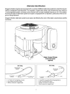
7 7. F. Setting the Low Idle RPM .. 7. G. Carburetor Fuel Mixture .. 7. H. Shutting the Engine Down .. 7. Tools Needed 1/4" wrench, or nut driver 3/8" - 7/16" wrench, or ratchet and socket Blade type screwdriver Torque wrench is required Tachometer 4. Magnum Twin Horizontal Engine Throttle Control Lever (Shown in Low Idle Position). Throttle Control Wire Throttle Cable (Under Cable Clamp). Constant Speed Control (When Remote Governor Cable is Not Used) Spring High Idle RPM. Stop Bracket Optional Throttle Cable Bracket Location High Idle RPM. Stop Bracket Screw Figure 1. Magnum Twin Horizontal Throttle Control . A. Throttle Control (Does not apply to customer 2. Engines with dome style air cleaner start supplied Control plate.)
8 With #3. 1. Engines with the square air cleaner assembly- Remove the two wing nuts (top of 3. Loosen the Throttle Control cable clamp located air cleaner cover), the cover, and the two on top of the intake manifold, or on the intake rubber seals, and then lift the element and dish manifold bracket, located to the right on one of out. the manifold mounting bolts. Disconnect the breather hose from the air 4. Position the application Throttle Control in the cleaner base by pushing downward. fast Throttle position. Then move the Throttle Control back 3/16" ( mm). Insert the Control Remove the air cleaner base 3/8" hex. head. cable bowden wire in the proper hole of the retaining screw, air cleaner base, and oval engine Control lever, which is located on air tube.
9 The side of the carburetor air intake elbow. Leave the air cleaner base gasket on the carburetor air cleaner elbow. 5. Magnum Twin Horizontal 5. Grasp the Control cable and place it under the 3. Position the Choke Control so it bottoms, cable clamp. Pull until the cable is taut, then then pull it back approximately 1/16" ( mm). tighten the clamp screw. NOTE: The engine Make sure that the carburetor Choke is fully Control lever should be against the high idle opened before tightening cable clamp. RPM stop bracket. 4. Reassemble all air cleaner components and 6. Move the application Throttle Control to the the crankcase breather tube. slow position, then to fast. Check the engine Control to assure it stops against the high idle C.
10 Starting the Engine RPM stop bracket. 1. Position the application Throttle Control to mid/full Throttle . NOTE: When the application Throttle Control lever is in the slow position the 2. Place the Choke Control into the on position. engine governor spring must be free of tension or pushing pressure. A non- 3. Turn the key switch or push the start button. free spring can affect the RPM. Release as soon as the engine starts. NOTE: Do not move the governor spring to 4. Push the Choke Control inward. If the engine other holes without approval. hesitates, pull the Choke Control out until the engine regains its momentum, then push the B. Choke Control (See Figure 2) Choke Control in again.