Transcription of Through Hole Solder Joint Evaluation - IPC
1 Association Connecting Electronics IndustriesTraining & Reference GuideThrough hole Solder Joint EvaluationIPC DRM-PTH-FReferences: IPC-A-610 Rev. F July 2014 IPC 2015 3000 Lakeside Drive, Suite 309-S Bannockburn, IL 60015-1219 +1 (tel.) +1 (fax) email: rights reserved under both international and Pan-American copyright conventions. Any copying, scanning or other repro-ductions of these materials without the prior written consent of the copyright holder is strictly prohibited and constitutes infringement under the Copyright Law of the United free images for page 10, Target; page 11, Target; page 19, lower Target; page 25, Acceptable Omni training , 9513 Business Center Dr., Suite J, Rancho Cucamonga, CA 91730, used by permission. IPC-DRM-PTH Rev. F 2m Rev. E 3m Rev. D 4m Rev. D 5m IPC-DRM-40 Rev. E 5m Rev. D 5m Rev. C 3m Rev.
2 B 3m Rev. A 5m 1st printing 1m Association Connecting Electronics IndustriesThrough hole Solder Joint Evaluation training and Reference Guide1 Solder DestinationSideBarrelSolder Source SideIntroduction & ClassificationIntroductionThis Through hole Solder Joint Evaluation training and Reference Guide provides visual examples of acceptability requirements, defects and conditions found in Through hole Solder joints on electronic assemblies. This manual is intended for use as an illustrated support document to assist in the training and practice of Through hole Solder Joint Evaluation , and therefore, it references portions of the fol-lowing IPC standard: The IPC-A-610 Rev. F, Acceptability of Electronic Assemblies, which illustrates the requirements for many types of Solder connections. ClassificationThrough hole Solder Joint requirements are divided into three classes depending on the ultimate use, life expectancy and operating environment of the electronic assembly.
3 Those classes are as follows:Class 1 General Electronic ProductsIncludes consumer type products suitable for applications where the major require-ment is the function of the completed assembly, not necessarily for extended life, reliability of service, or cosmetic 2 Dedicated Service Electronic ProductsIncludes commercial type products where continued performance and extended life is required and for which uninterrupted service is desired but not critical. Typically, the end use environment would not cause failures Through extremes of temperature or 3 High Performance Electronic ProductsIncludes products where continued high performance or performance-on-demand is criti-cal, equipment downtime cannot be tolerated, end-use environment may be uncommonly harsh, and the equipment must function when required. These high-reliability type prod-ucts are used in such systems as life-support and : The inspector does not select the class for the part under inspection.
4 Documentation which specifies the applicable class for the part under inspection should be provided to the of Contents22355678910111213141516171819202 12223242526272829 Introduction ClassificationTerminologyAcceptance CriteriaLead FreeCondition LevelsLand CoverageExcess SolderVertical Fill Wetting, Lead & BarrelWetting of Lead, Land & BarrelContact AngleDiscerning the LeadSolder BallsSolder BridgingCavitiesCold Solder JointCoating Meniscus in Solder JointCorrosion / Surface AppearanceDisturbed Solder Joint Exposed Basis MetalForeign Object Debris (FOD)Lead Cutting/Fractured Solder JointLead ProtrusionLead Protrusion / ClinchedNonwetting of Solder Projections ResidueSplashes of Solder / Webbing Dimensional CriteriaSolder ConditionsPageThrough hole Solder Joint Evaluation training and Reference Guide2 Through hole Solder Joint Evaluation training and Reference Guide3 TerminologyTerminologySolder Destination Side: The side of a Through hole assem-bly containing the most com-ponent bodies.
5 Also called the primary side or sometimes the component side. Cross-section View of a Target Plated - Through HoleSolder Source Side: The side that is coated with Solder in the Solder wave machine. Also called the secondary side. Below are the definitions of terms you will run across while using this manual: (taken from IPC-T-50, Terms and Definitions for Interconnecting and Packaging Electronic Circuits)Clinched Lead - A component lead that is inserted Through a hole in a PWB and is then bent or clinched to hold the component in place and to make metal-to-metal contact with a land before Solder Connection - A Solder connection that exhibits poor wetting, and that is characterized by a gray, porous - An individual part or combination of parts that, when together, perform a design - A single conductive (metal) path in a conductive angle - The angle formed by the edge of the Solder fillet and the land s - A condition that results when molten Solder coats a surface and then recedes to leave irregularly-shaped mounds of Solder that are separated by area that are covered with a thin film of Solder and with the basis metal not Solder connection - A Solder connection that is characterized by the appearance that there was motion between the metals being joined when the Solder was Solder connection - A Solder connection that is characterized by the complete obscuring of the surfaces of the connected metals and/or by the presence of Solder beyond the connection - A normally-concave surface of Solder that is at the intersection of the metal surfaces of a Solder residue - A flux-related contaminant that is present on or near the surface of a Solder ( Solder )
6 Projection) - An undesirable protrusion of Solder from a solidified sol-der Joint or - A portion of a conductive pattern that is usually used for making electrical connections, for component attachment, or - The wire or formed metal conductor that extends from a component to serve as a mechanical and/or electrical - The partial adherence of molten Solder to a surface that it has con-tacted and basis metal remains - A small hole that penetrates from the surface of a Solder connection to a void of indeterminate size within the Solder hole - A hole with plating on its walls (supported hole ) that makes an electrical connection between conductive patterns on internal layers, external layers, or both, of a printed - Any visual or measurable form of process-related - A metal alloy with a melting temperature that is below 427 C (800 F).Solderability - The ability of a metal to be wetted by molten - The joining of metallic surfaces with Solder and without the melting of the base bridging - The unwanted formation of a conductive path of Solder between - Extraneous fragments of Solder with an irregular - A continuous film or curtain of Solder that is parallel to, by not necessarily adhering to, a surface that should be free of - The formation of a relatively uniform, smooth, unbroken, and adherent film of Solder to a basis Destination SideBarrelSolder Source SideThrough hole Solder Joint Evaluation training and Reference Guide4 Through hole Solder Joint Evaluation training and Reference Guide6 Through hole Solder Joint Evaluation training and Reference Guide5 Acceptance CriteriaIn this training and Reference Guide.
7 Criteria are given for each class in one or more of the following levels of condition Photographs or illustrations of each condition are shown in the left column (examples on opposite page). The level of acceptance, class(es) and descrip-tion of the illustration are all contained in the right column. In the following examples, definitions of each acceptance criterion are printed to the right of sample photographs. For easier viewing, colored bars connect each photo-graph or illustration to each description, with a different color used for each acceptance : Accept and/or reject decisions must be based on applicable documentation such as contract, drawings, specifications such as IPC-A-610 and IPC J-STD-001 or other referenced Free SolderingThe primary difference between the Solder connections created with processes using tin-lead alloys and processes using lead free alloys is related to the visual appear-ance of the lead free and tin-lead connections may exhibit similar appearances, but lead free alloys are more likely to have: - Surface roughness (grainy or dull) - Greater wetting contact angles*All other Solder criteria are the same.
8 *Wetting cannot always be judged by surface appearance. The wide range of Solder alloys in use may exhibit from low or near zero degree contact angles to nearly 90 degree contact angles as typical. Pb Denotes Lead FreeA defect is a condition that is insufficient to ensure the form, fit or function of the assembly in its end use environment. The manufacturer shall rework, repair, scrap, or use as is based on design, service and customer Class 1, 2, 3 Target Class 1, 2, 3 Process Indicator Class 1, 2, 3 Defect Class 1, 2, 3A process indicator is a condition that does not affect the form, fit and function of a product. However, process indicators signal a lack of good workmanship to the customer and should be used to improve the manufacturing process even though the product is considered characteristic indicates a condition that, while not necessarily perfect, will maintain the integrity and reliability of the assembly in its service environment.
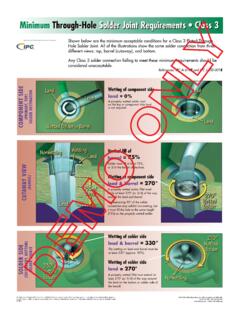
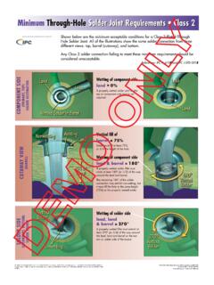
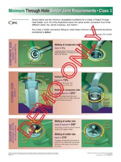
9 A condition that is close to perfect; how-ever, it is a desirable condition and not always achievable and may not be neces-sary to ensure reliability of the assembly in its service LevelsAcceptableTargetProcess IndicatorDefectThrough hole Solder Joint Evaluation training and Reference Guide8 Through hole Solder Joint Evaluation training and Reference Guide7 Defect Class 1, 2, 3 References: A-610F: , Table 7-40% of the Solder destination side land area is covered with wetted wetted Solder fillet covers 100% of Solder destination side land area and feathers out to a thin edge on land Destination Side - Excess SolderSolder Destination Side - Land CoverageSolder in lead bend area comes in contact with the component body or end seal; or obscures the stress relief bend of the component : A-610F: , in lead bend area does not contact the component body or end does not obscure the stress relief bend of the component fillet ends below lead bend Class 1, 2, 3 Target Class 1, 2, 3 Acceptable Class 1, 2, 3 Target Class 1, 2, 3 Through hole Solder Joint Evaluation training and Reference Guide10 Through hole Solder Joint Evaluation training and Reference Guide9A minimum of 180 circumferential wetting (50%) present on Solder destination side of lead and barrel.
10 Vertical fill at 75%.A minimum of 270 circumferential wetting (75%) present on Solder destination side of lead and barrel. Vertical fill at 75%.Note:Minimum acceptable condition for cir-cumferential wetting of lead and barrel on Solder destination side for Class 1 is not : A-610F: , Table 7-4100% (360 ) circumferential wetting pres-ent on Solder destination side of lead and barrel. Vertical fill at 100%.Notes:Minimum acceptable condition for vertical fill of Solder on Class 1 assemblies is not specified. Less than 100% Solder fill may not be acceptable in some applications, , thermal shock, electrical : A-610F: , Table 7-4 Vertical fill at a minimum of 50%, or mm [ in], whichever is less, is accept-able for Class 2 components of 14 leads or more; less than 75% vertical fill is a defect for Class 3 Solder joints, and Class 2 Solder joints on components of less than 14 minimum of 75% Solder fill, or a maximum of 25% depression, including both Solder source and Solder destination sides, is permitted.