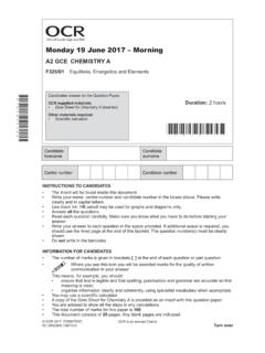
Transcription of Thursday 9 June 2016 – Afternoon
1 Thursday 9 june 2016 AfternoonAS GCE PHYSICS AG482/01 Electrons, Waves and PhotonsINSTRUCTIONS TO CANDIDATES Write your name, centre number and candidate number in the boxes above. Please write clearly and in capital letters. Use black ink. HB pencil may be used for graphs and diagrams only. Answer all the questions. Read each question carefully. Make sure you know what you have to do before starting your answer. Write your answer to each question in the space provided. If additional space is required, you should use the lined page at the end of this booklet.
2 The question number(s) must be clearly shown. Do not write in the bar FOR CANDIDATES The number of marks is given in brackets [ ] at the end of each question or part question. The total number of marks for this paper is 100. You may use an electronic calculator. You are advised to show all the steps in any calculations. Where you see this icon you will be awarded marks for the quality of written communication in your answer. This means for example you should: ensure that text is legible and that spelling, punctuation and grammar are accurate so that meaning is clear; organise information clearly and coherently, using specialist vocabulary when appropriate.
3 This document consists of 20 pages. Any blank pages are indicated.*G48201*OCR is an exempt CharityTurn over OCR 2016 [L/500/8055]DC (CW/SW) 67347/6 Candidates answer on the Question supplied materials: Data, Formulae and Relationships Booklet(sent with general stationery)Other materials required: Electronic calculator*1164935362*Duration: 1 hour 45 minutesOxford Cambridge and RSA2 OCR 2016 Answer all the (a) Write a suitable word equation to define the resistivity of a material..[1] (b) A student investigates the electrical properties of the graphite lead in a pencil.
4 (i) The pencil is 150 mm long. The lead is a cylindrical graphite rod of diameter mm. The resistance of the rod is . Calculate the resistivity of graphite. = .. unit .. [4] (ii) The graphite rod is removed from the pencil and used as a variable resistor, labelled in the circuit of Fig. At a particular point X the current in ammeter A1 is twice the current in ammeter VA2A1 Fig. over OCR 2016 1 Explain why X must be the mid point of the graphite rod.
5 [3] 2 Calculate the current in A1. current = .. A [2] (c) Calculate the mean drift velocity v of the free electrons in the graphite rod when there is a current of A in it. number of charge carriers per unit volume = 1026 m 3 v = .. m s 1 [3]4 OCR 2016 (d) A metal such as copper is classified as a conductor. Graphite behaves as a semiconductor. (i) Describe why the resistivity of copper is less than that of graphite..[2] (ii) State with a reason what effect an increase in temperature has on the electrical properties of each of these two types of material.
6 [2]5 Turn over OCR 20162 Fig. shows the I-V characteristic of a light-emitting diode (LED) which is designed to light normally at a current of 30 / / (a) (i) On Fig. draw the I-V characteristic of a fixed resistor of resistance 67 . [2] (ii) Explain how the I-V characteristics show that the resistor obeys Ohm s law but the LED does not..[2]6 OCR 2016 (b) The LED and 67 resistor are connected in series to a V supply of negligible internal resistance.
7 (i) Show that the LED lights normally, with a current of 30 mA. [3] (ii) Calculate 1 the charge Q passing through the LED each second Q = .. C [1] 2 the energy required to light the LED each second energy = .. J [2] 3 the energy dissipated in the resistor each second. energy = .. J [2]7 Turn over OCR 2016 (iii) Seven of these LEDs, each with its 67 series resistor, are arranged in a unit as shown in Fig. to display any number from 0 to Three of these units enable numbers up to 999 to be displayed.
8 The three number display is connected to the V supply so that all the LED-resistor combinations are in parallel. Each three number display is provided with a fuse. Circle the most suitable value for the fuse from the list below and give a reason for your mA 500 mA A A ..[2] (c) Give one other example where LEDs are now commonly used. Suggest one advantage of using LEDs in place of filament lamps..[2]8 OCR 20163 (a) Circle the quantity, in the list below, that is conserved in Kirchhoff s second law.
9 Charge energy current [1] (b) Explain the meaning of the following terms which are often used when referring to a supply (i) terminal potential difference ..[2] (ii) internal resistance..[1] (c) Fig. shows a supply labelled V connected to a circuit containing an ammeter, a voltmeter, a fixed resistor and a 0 to 15 variable resistor. You are to carry out an experiment to show that the internal resistance r of the supply is constant for a range of currents and to find the value of 1 VrAVFig.
10 Over OCR 2016 (i) Describe how you would carry out the experiment. Explain how you would determine the value of the internal resistance of the supply and show that it is constant..[5] (ii) Suggest why the resistor is included in the circuit..[1]10 OCR 2016 (d) Two cells X and Y each have an and internal resistance as shown in Fig. They are connected in series to a resistor R of resistance . 1R = VFig. (i) Note that the positive terminals of the cells are connected together.
