Transcription of Timber frame structures – platform frame construction (part 1)
1 IntroductionThe platform frame method of building Timber frame structures is suited to both low-rise and medium-rise buildings. Many buildings up to six and seven storeys in height have been constructed over recent years typically for residential, institutional and hotel are a number of diff erent conditions that need to be satisfied by the structural engineer during the engineering of a multi-storey Timber frame building, including: The adequacy of vertical load paths The strength and stiff ness of the individual framing members Overall building stability and stability of the individual elements Robustness of the framing and connections Disproportionate collapse designThis article introduces the composition and terminology used for platform Timber frame building structures and describes the structural engineering checks which are required to verify the adequacy of the vertical load paths and the strength and stiffness of the individual framing members.
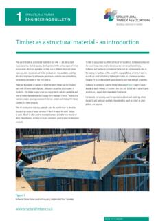
2 There are several parts to the Engineering Bulletin for platform Timber frame structures . Part 2 will cover horizontal stability, while part 3 will cover robustness and disproportionate collapse formThe term platform frame derives from the method of construction where floor structures bear onto loadbearing wall panels, thereby creating a platform for construction of the next level of wall panels, as indicated in Figure 1. platform frame construction is particularly suited to buildings that have a cellular plan form. Internal walls may be used to contribute to this cellular layout and are used as loadbearing elements for resistance to both vertical and horizontal loads. Vertical actions from walls, fl oors and roofs are supported by Timber wall panels comprised of vertical studs at regular centres (typically 600mm centres or closer) that act as vertical columns.
3 An example calculation can be found in the Worked example 0 - frame structures platform frame construction (part 1) TIMBERENGINEERING BULLETIN3 Figure 1 Structural concept of platform Timber frame TIMBERENGINEERING BULLETIN32 REV 0 - external wall studs are 140mm x 38mm (the 140mm dimension often being required to accommodate the minimum building regulation thermal insulation, although other means of achieving this with small depth studs are available) and internal wall studs 89mm x 38mm. These studs may be structurally connected to provide columns of wider sections or replaced by larger Timber sections such as glulam posts (or in some cases steel posts) to resist high point to horizontal actions is provided by the in-plane shear resistance (or racking resistance) of sheathed wall panels which are connected together to act as contiguous wall diaphragms.
4 Racking resistance is covered in part termsTimber frame constructions can utilise factory assembled wall panels together with fl oor and roof panels often referred to as cassettes . Where off-site manufacturing of panels and cassettes are used, STA quality approval (leading to CE marking where appropriate) is required. The off-site assembled panels and cassettes may be made with joists or studs partially or fully clad, with solid panels such as cross laminated Timber or composite insulation/ Timber structurally insulated panels. Open panels are Timber frame wall panels comprising studs, rails, sheathing on one face and breather membrane (Figure 2).Closed panels are Timber frame wall panels comprising studs, rails and insulation with sheathings and/or linings on the faces of the panel; a vapour barrier is provided on the warm side of the insulation and a breather membrane on the outer face of the panel (Figure 3).
5 Closed panels may also include fitted windows and internal service zone cassettes are fully assembled groups of joists, rimboards or rimjoists with structural subdeck fitted to enable lifting as a completed assembly (Figure 4). Treatments to the timbers are often coloured for differentiation. Floor cassettes may also include fitted insulation and lining laminated Timber (CLT) is a solid panel product made by laminating small lengths of Timber , usually kiln-dried spruce, with adjacent layers having their grain direction at right angles to one another. These large solid panels can be used to form beams, columns, walls, roofs, floors and even lift shafts and stairs. CLT is a solid panel, capable of resisting comparatively high racking and vertical loads (Figure 5).Structural insulated panels (SIPs) are factory-produced, prefabricated building products that can be used as load bearing or infill wall panels, floor Figure 2 Lintels in an open panel Timber frame wall panelFigure 4 Erection of a prefabricated flame retardant floor cassetteFigure 3 Sheathed Timber frame closed panel with service battensFigure 5 CLT wall panel TIMBERENGINEERING BULLETIN33 REV 0 - roof components in platform frametype construction .
6 The benefit of the system is that the structural support and the insulation are incorporated into a single system during manufacture. This results in material efficiency but care is need for concentrated loading on the frame wall panels and floor cassettes are usually obtained from a specialist manufacturer such as a member of the STA ( )Elements of a Timber frameComponents of Timber floors Floor joists in platform Timber frame structures (Figure 6a and b) can be either softwood joists or a range of engineered wood products. More detail on EWPs can be found in Engineering Bulletin No. 2. Examples of typical floor zone details are shown in Fig of Timber frame wall panels The loadbearing elements of a Timber frame wall panel (Figure 7) typically comprise the following components.
7 Wall studs which are vertical Timber members carrying axial loads and lateral loads from wind pressures Top and bottom wall panel rails (usually of the same section size as the studs) which connect the studs together as a panel Soleplates or starter plates which are fixed to the foundation or subdeck to provide a locating position for the wall panel Headbinders or header plates which connect together adjacent wall panels to enable them to function as a continuous wall diaphragm and, in combination with the top wall panel rails, act as spreader beams to distribute floor joist loads to the wall studs where the joists are not aligned (noded) with the studs. Headbinders are usually site-fitted Lintels, cripple studs and opening studs which transfer vertical and horizontal loads around openings in the wall panels.
8 The studs are typically arranged so that their stronger axis (y-y) is parallel to the face of the wall (Figure 8).Principle design code references The limit state codes for Timber engineering are BS EN 1995-1-1 Eurocode 5: Design of Timber structures Part 1-1, together with the UK National Annex to Eurocode 5: BS EN 1995-1-1: Design of Timber structures Part 1-1 and PD6693-1:2012 UK Non-Contradictory Complementary Information (NCCI) to Eurocode 5268-2:2002 and both BS (wall panels up to m height) and BS (wall panels up to height) have been used to design Timber structures in the UK on a permissible stress basis, though they are limited to seven and four storeys 6a Floor joists perpendicular to external wall panel Figure 6b Floor joists parallel to external wall panelFigure 7 Typical Timber frame wall panels showing component notationFigure 8 Wall stud plan view and TIMBERENGINEERING BULLETIN34 Table 1.
9 Typical platform frame materialsREV 0 - Bulletin concentrates only on the use of Eurocode 5 for the design of platform frame constructions, as the British Standard has now been superseded by the height limit of seven storeys has, in the past, been determined by the structural robustness relating to the vertical movement and racking stiff ness and serviceability design, using working stress designs. Applying the principles of Eurocode 5 and using high strength materials such as cross laminated Timber (CLT) it is possible to build higher than seven storeys provided particular attention is given to connections and bearing pressures beneath wall panels. In-service fi re resistance of frames increases with building height and the engineer should always consider fire resistance of the frame in the design approach.
10 Other Bulletins will address fire and Timber designing Timber structures and carrying out code checks, care is needed to ensure that the factors used in equations are consistent with the code of practice being used. Using a combination of Eurocodes and British Standards on a structure can lead to an unsafe assessment as the two codes are based on fundamentally different Timber platform frame construction typically uses softwood wall studs and rails together with a wood-based sheathing board (in accordance with BS EN 13986:2004 see Engineering Bulletin No. 2 for further information) to form a structural frame which transmits all vertical and horizontal loads acting on the structure, safely to the building s 9 Vertical structural load paths in platform Timber frame TIMBERENGINEERING BULLETIN35 REV 0 - contribution of plasterboard to racking resistance may also be considered within the limits allowed by PD6693-1 platform frame materials and the loadbearing elements of a Timber frame wall panel are indicated in Table 1 and Fig.