Transcription of Time of Concentration - Institute for Transportation
1 2B-3 Design Manual Chapter 2 - Stormwater 2B - Urban Hydrology and Runoff Time of Concentration 1 Revised: 2013 Edition A. Introduction Time of Concentration (Tc) is the time required for runoff to travel from the hydraulically most distant point in the watershed to the outlet. The hydraulically most distant point is the point with the longest travel time to the watershed outlet, and not necessarily the point with the longest flow distance to the outlet. Time of Concentration is a critical component in some analysis methods for calculating peak discharge from an area. The peak discharge occurs when all segments of the drainage area are contributing to the runoff from the site.
2 There are many methods available to estimate the time of Concentration including the Kirpich formula, Kerby formula, NRCS Velocity Method, and NRCS Lag Method. The NRCS Velocity and Lag methods are two of the most commonly used methods for determining time of Concentration and are described below. B. Factors Affecting Time of Concentration 1. Surface Roughness: One of the most significant effects of urban development on overland flow is the lowering of retardance to flow causing higher velocities. Undeveloped areas with very slow and shallow overland flow (sheet flow and shallow concentrated flow) through vegetation become modified by urban development.
3 Flow is then delivered to streets, gutters, and storm sewers that transport runoff downstream more rapidly. Travel time through the watershed is generally decreased. 2. Channel Shape: In small non-urban watersheds, much of the travel time results from overland flow in upstream areas. Typically, urbanization reduces overland flow lengths by conveying storm runoff into a channel as soon as possible. Since channel designs have efficient hydraulic characteristics, runoff flow velocity increases and travel time decreases. 3. Slope: Slopes may be increased or decreased by urbanization, depending on the extent of site grading or the extent to which storm sewers and street ditches are used in the design of the water management system.
4 Slope will tend to increase when channels are straightened and decrease when overland flow is directed through storm sewers, street gutters, and diversions Urbanization usually decreases time of Concentration , thereby increasing the peak discharge. However, time of Concentration can be increased as a result of ponding behind small or inadequate drainage systems (including inlets and road culverts) or by reduction of land slope through grading. Chapter 2 - Stormwater Section 2B-3 - Time of Concentration 2 Revised: 2013 Edition C. NRCS Velocity Method The NRCS Velocity method is described in full detail in NRCS TR-55. Travel time (Tt) is the time it takes water to travel from one location to another.
5 The travel time between two points is determined using the following relationship: = 3,600 Equation where: Tt = travel time, hours = flow length, ft V = average velocity, ft/s 3,600 = conversion factor, seconds to hours Surface water flow through the watershed occurs as three different flow types: sheet flow, shallow concentrated flow, and open channel flow. The NRCS Velocity Method assumes that time of Concentration (Tc) is the sum of travel times for each of these flow segments along the hydraulically most distant flow path. = + + Equation where: Tc = time of Concentration , hours Ts = travel time for sheet flow, hours Tc = travel time of shallow concentrated flow, hours To = travel time for open channel flow, hours 1.
6 Sheet Flow: Sheet flow is defined as flow over plane surfaces. Sheet flow usually occurs in the headwaters of a stream near the ridgeline that defines the watershed boundary. Typically, sheet flow occurs for no more than 100 feet before transitioning to shallow concentrated flow. A simplified version of the Manning s kinematic solution may be used to compute travel time for sheet flow. = ( ) ( 2) Equation where: Tt = travel time, h n = Manning s roughness coefficient (Table ) = sheet flow length, ft P2 = 2 year, 24 hour rainfall, in S = slope of land surface, ft/ft Chapter 2 - Stormwater Section 2B-3 - Time of Concentration 3 Revised: 2013 Edition Table : Manning s Roughness Coefficient for Sheet Flow Surface Description n Smooth Surface (concrete, asphalt, gravel, or bare soil).
7 Fallow (no residue) .. Cultivated Soils: Residue cover < 20% .. Residue cover > 20% .. Grass: Short grass prairie .. Dense grasses1 .. Bermudagrass .. Range (natural) .. Woods:2 Light underbrush .. Dense underbrush .. 1 Includes species such as weeping lovegrass, bluegrass, buffalo grass, blue grama grass, and native grass mixtures. 2 When selecting n, consider cover to a height of about foot. This is the only part of the plant cover that will obstruct sheet flow. 2. Shallow Concentrated Flow: After approximately 100 feet, sheet flow usually becomes shallow concentrated flow collecting in swales, small rills, and gullies.
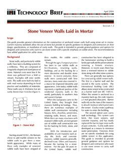
8 Shallow concentrated flow is assumed not to have a well-defined channel and has flow depth of to feet. It is assumed that shallow concentrated flow can be represented by one of seven flow types. These flow types are shown in Figure and Table After estimating average velocity using Figure or the equations from Table , use Equation to estimate travel time for the shallow concentrated flow segment. Chapter 2 - Stormwater Section 2B-3 - Time of Concentration 4 Revised: 2013 Edition Figure : Velocity Versus Slope for Shallow Concentrated Flow Source: NRCS National Engineerining Handbook, Part 630, Chapter 15 Table : Equations and Assumptions Developed from Figure Flow Type Depth (feet) Manning s n Velocity Equation (ft/s) Pavement and small upland gullies = ( ) Grassed waterways (and unpaved urban areas) = ( ) Nearly bare and untilled (overland flow).
9 And alluvial fans = ( ) Cultivated straight row crops = ( ) Short-grass prairie = ( ) Minimum tillage cultivation, contour or strip-cropped, and woodlands = ( ) Forest with heavy ground litter and hay meadows = ( ) Chapter 2 - Stormwater Section 2B-3 - Time of Concentration 5 Revised: 2013 Edition 3. Open Channel Flow: Open channels (swales, ditches, storm sewers, and tiles not flowing full) are assumed to begin where surveyed cross-sectional information has been obtained, where channels are visible on aerial photographs, or where blue lines (indicating streams) appear on Geological Survey (USGS) quadrangle sheets.
10 Manning s equation or water surface profile information can be used to estimate average flow velocity. Average flow velocity is usually determined for the bankfull elevation. Manning s equation is: = ( 23)( 12) Equation where: V = average velocity, ft/s R = hydraulic radius, ft = / a = cross-sectional areas of flow, ft2 P = wetted perimeter, ft s = slope of the hydraulic grade line (channel slope), ft/ft n = Manning s value for open channel flow Refer to Parts 2D (Storm Sewer Design), 2E (Culvert Design), or 2F (Open Channel Flow) for additional details on evaluating flow velocity for open channel flow. Chapter 2 - Stormwater Section 2B-3 - Time of Concentration 6 Revised: 2013 Edition Table : Manning s Roughness Coefficients (n) for Open Channel Flow Type of Channel and Description n A.