Transcription of Timers Multifunction Types DMB51, DMB71 - Carlo Gavazzi
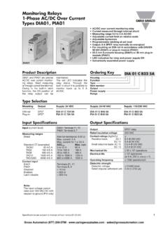
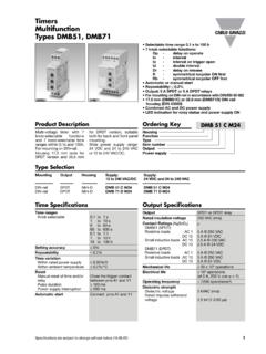
1 Timers Multifunction Types dmb51 , DMB71 . Selectable time range s to 100 h 7 knob selectable functions: Op - delay on operate In - interval Io - interval on trigger open Id - double interval Dr - delay on release R - symmetrical recycler ON first Rb - symmetrical recycler OFF first Automatic or manual start Repeatability: Output: 5 A SPDT or 5 A DPDT relays For mounting on DIN-rail in accordance with DIN/EN 50 022. dmb51 DMB71 mm (DMB51C) or mm (DMB71D) DIN-rail housing (DIN 43880). Combined AC and DC power supply LED indication for relay status and power supply ON. Product Description Ordering Key DMB 51 C M24. Multi-voltage timer with 7 for DPDT version, suitable Housing knob-selectable functions both for back and front panel Function and 7 knob-selectable time mounting.
2 Type ranges within and 100h. Wide power supply range: Item number For mounting on DIN-rail. 24 VDC and 24 to 240 VAC Output Housing mm wide for or 12 to 240 VAC/DC. Power supply SPDT version and mm Type Selection Mounting Output Housing Supply: Supply: 12 to 240 VAC/DC 24 VDC and 24 to 240 VAC. DIN-rail SPDT Mini-D DMB 51 C W24 DMB 51 C M24. DIN-rail DPDT Mini-D DMB 71 D W24 DMB 71 D M24. Time Specifications Output Specifications Time ranges Output SPDT or DPDT relay Knob selectable to 1 s Rated insulation voltage 250 VAC (rms). 1 to 10 s 6 to 60 s Contact Ratings (AgSnO2) . 60 to 600 s Resistive loads AC 1 5 A @ 250 VAC. to 1 h DC 12 5 A @ 24 VDC. 1 to 10 h Small inductive loads AC 15 A @ 250 VAC.
3 10 to 100 h DC 13 A @ 24 VDC. Setting accuracy 5% Mechanical life 30 x 106 operations Repeatability Electrical life 105 operations (at 5 A, 250 V, cos = 1). Time variation Within rated power supply Operating frequency < 7200 operations/h Within ambient temperature C Dielectric strength Reset Dielectric voltage 2 kVAC (rms). Manual reset of time and/or Close the trigger contact Rated impulse withstand relay between pins A1 and Y1 voltage kV ( s). Pulse duration 100 ms Power supply interruption 200 ms Automatic start Connect pins A1 and Y1. Specifications are subject to change without notice ( ) 1. Gross Automation (877) 268-3700 dmb51 , DMB71 . Supply Specifications General Specifications Power supply Overvoltage cat.
4 II Power ON delay 100 ms Rated operational voltage (IEC 60664, IEC 60038) Indication for through terminals: Power supply ON LED, green (DMB51C) A1, A2 M24: 24 VDC 15% and Output relays ON LED, yellow 24 to 240 VAC + 10% -15%, (flashing when timing). 45 to 65 Hz W24: 12 to 240 VDC + 10% -15% Environment (EN 60529). and Degree of protection IP 20. 12 to 240 VAC Pollution degree 2 (IEC 60664). + 10% -15%, 45 to 65 Hz Operating temperature -20 to +60 C, < 95%. (DMB71D) A1, A2 M24: 24 to 240 VDC + 10% -15% Storage temperature -30 to +80 C, < 95%. 24 to 240 VAC + 10% -15%, Housing dimesions 45 to 65 Hz (DMB51C) x 81 x mm W24 12 to 240 VDC + 10% -15% (DMB71D) x 81 x mm and Weight 75 g 12 to 240 VAC +10% -15%, Screw terminals 45 to 65 Hz Tightening torque Max.
5 Nm according to Voltage interruption 10 ms IEC EN 60947. Rated operational power Approvals UL, CSA (DMB 51 only), (DMB51C) AC supply: 4 VA RINA (DMB 51 only). DC supply: W CE Marking Yes (DMB71D) AC supply VA. DC supply 2W EMC Electromagnetic Compatibillity Immunity According to EN 61000-6-2. Emissions According to EN 50081-1. Time Setting Upper knob: Centre knob: Setting of function: Time setting on relative scale: Op - delay on operate 1 to 10 with respect to the In - interval chosen range. Io - interval on trigger open Lower knob: Id - double interval Setting of time range Dr - delay on release R - symmetrical recycler (ON first). Rb - symmetrical recycler (OFF first). Mode of Operation Function Op the end of this period or is opened before the end of the second time period the Delay on operate when the power supply is the delay time the relay device resets and the first The time period begins as disconnected.
6 The relay keeps ON and a new time time period begins again. soon as the trigger contact operates again when the trig- period begins. is closed. ger contact is closed again. If Function Dr At the end of the set delay the trigger contact is closed Function Id Delay on release time the relay operates and before the end of the delay Double interval The relay operates as soon does not release until the time, the device resets and a The relay operates and the as the trigger contact is trigger contact is closed new time period starts. time period begins as soon closed. The time period again or the power supply is as the trigger contact is begins when the trigger con- disconnected. If the trigger Function Io closed.
7 The relay releases at tact is opened. The relay contact is closed before the Interval on trigger open the end of this period or releases at the end of the end of the delay time, the The relay operates and the when the power supply is set delay time or when the device resets and a new time period begins as soon disconnected. When the power supply is disconnect- time period starts. as the trigger contact is trigger contact is opened ed. The relay operates again opened. At the end of the the relay operates again for when the input contact is Function In set delay or when the power the set delay period. If the closed again. If it is opened Interval supply is disconnected the trigger contact is opened before the end of the delay The relay operates and the relay releases.
8 The relay before the end of the first time the relay keeps ON, a time period begins as soon operates again when the time period the second one new time period begins as as the trigger contact is trigger contact is opened begins; if the trigger contact soon as the contact is closed. The relay releases at again. If the trigger contact is closed before the end of closed again. 2 Specifications are subject to change without notice ( ). Gross Automation (877) 268-3700 dmb51 , DMB71 . Mode of Operation (cont.). Function R Function Rb Additional Load Yellow LED working Symmetrical recycler, ON- Symmetrical recycler, It's possible to wire an addi- mode time period first OFF-time period first tional load ( a relay) Timing: Slow blinking The relay operates and the The time period begins as between pins Y1 and A2, Relay ON: See operation time period begins as soon soon as the input contact is driven by the trigger contact diagrams as the input contact is closed.
9 The relay is OFF without damaging the closed. After the set delay during the set delay period, device. Incorrect knobs position: period the relay releases for after this time it operates for Fast blinking the same time period. This the same time period. This sequence continues with sequence continues with equal ON- and OFF-time equal OFF- and ON-time periods until the power sup- periods until the power sup- ply is interrupted. ply is interrupted. Wiring Diagram L(+).. A1 16 18 26 28. S. Y1. A2 15 25. N(-). Operating Diagrams Function Op - Delay on operate - Manual start Function In - Interval - Manual start Power supply Power supply Trigger input Trigger input ON T T ON T T.
10 Relay ON Relay ON. OFF OFF. LED LED. Function Op - Delay on operate - Automatic start Function In - Interval - Automatic start Power supply Power supply ON T T ON T T. Relay ON Relay ON. OFF OFF. LED LED. Specifications are subject to change without notice ( ) 3. Gross Automation (877) 268-3700 dmb51 , DMB71 . Operating Diagrams (cont.). Function Io - Interval on trigger open Function Id - Double interval Power supply Power supply Trigger input Trigger input ON T T ON T T. Relay ON Relay ON. OFF OFF. LED. LED. Function Dr - Delay on release Function R - Symmetrical recycler (ON first). Power supply Power supply Trigger input Trigger input ON T ON T T T T. Relay ON Relay ON. OFF OFF.