Transcription of Timing Jitter Dictionary and Measurement - Silicon Labs
1 Timing Jitter Dictionary and MeasurementJames WilsonMarketing Director, Timing | of Contents Types of Jitter Random Jitter Deterministic Jitter Correlated and Uncorrelated Jitter Types of Jitter Measurements Overview of Jitter Measurements Cycle-to-Cycle Jitter Period Jitter TIE Jitter or Phase Jitter Jitter Measurement Units Time vs. Frequency Domain Jitter vs. Phase noise Time Domain Equipment Frequency Domain Equipment Converting Between Time and Frequency Domain (RMS to peak-to-peak) Time vs. Frequency Domain Examples Calculating Spur Jitter Contribution Skyworks Timing Solutions Additional Resources | 3 Introduction The demand for near instant data access is increasing exponentially. High data rate applications like video, in conjunction with growing numbers of devices connected to each other, the Cloud and the Internet, are driving usage ever higher.
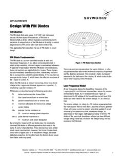
2 Likewise, users expect to upload and download high-density data in real-time, abandoning web sites almost immediately if the speed is trends are increasing the need for higher speed, higher bandwidth networks with higher data rates, and faster data interfaces. As speeds increase, the clocks and timingcomponents that support them must provide better Timing is the measure of Timing performance. High Jitter means poor Timing performance in most primer provides an overview of Jitter and offers practical assistance in taking Jitter | of Jitter Jitter falls into two broad categories: random Jitter and deterministic Jitter *.Random JitterRandom Jitter is a broadband stochastic** Gaussian process that is sometimes referred to as intrinsic noise because it is present in every system. In the various phase noise plots shown later in this document the relatively smooth sections along the bottom represent the intrinsic noise floor and are indicative of random Jitter .
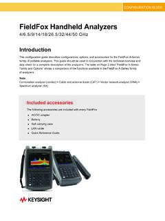
3 *Links to additional, more detailed information is available in the documents referenced in the Additional Resources page. **Words in blue are defined in the Jitter (Gaussian) | 5 Random Jitter s instantaneous noise value is mathematically unbounded. Looking at the random Jitter Gaussian curve below, the two tails extending away from the center approach zero, but never fully reach the probability of some values is very small, it is not zero, and therefore Jitter can be a significant contributor to overall system Jitter . However, it is unbounded and intrinsic to each system and is hard to diagnose and Distribution of Random Jitter6 | JitterDeterministic Jitter is not random or intrinsic to every system. It has a specific cause and is often periodic and narrowband. This means it is repetitious at one or more frequencies. Therefore, deterministic Jitter is typically identifiable and can be Jitter can be further subclassified into periodic Jitter and data-dependent Jitter .
4 Jitter from a switching power supply is periodic and deterministic because it has the same, periodic frequency as the switching power contrast, intersymbol interference (ISI) is an example of data-dependent Jitter from an isochronous 8B/10B coded serial data stream ( , Ethernet or PCI Express). These protocols use dynamically changing duty cycles and irregular clock edges, which contribute to overall Jitter (Gaussian) | 7 Data-dependent Jitter Measurement varies by system, functionality, and other factors, and are not specifically addressed in this and Uncorrelated JitterCorrelated Jitter on a clock is deterministic and always caused by and correlated to a noise source. An example of correlated Jitter is periodic Jitter , as in the case of a system power supply. However, correlated Jitter can be aperiodic. An example of correlated aperiodic Jitter is interference on a clock from a serial line.
5 The interference is correlated to the serial data line, but the serial data may be either periodic or Jitter is not statistically connected to an identifiable noise source. Random Jitter is always uncorrelated; however, some correlated Jitter may appear to be uncorrelated or random. This may occur when several noise sources overlap one another, causing their correlated Jitter to appear uncorrelated. These noise sources are often difficult to Jitter Intrinsic noise present in every system Also known as random Jitter Statistically unrelated to an identifiable noise source Can be a significant contributor to overall system jitterCorrelated Jitter Statistically identifiable as coming from a specific noise source Typically periodic but can also be aperiodic, making it difficult to diagnose More than one noise source may cause correlated Jitter seem uncorrelated8 | of Jitter Measurements Overview Types of Jitter MeasurementsAt a high level, there are three primary measurements for clock Jitter .
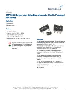
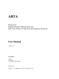
6 Each type of Measurement applies to various applications with different Timing performance with the most stringent requirements almost always specify maximum Time Interval Error (TIE) Jitter and phase noise , and may include requirements for period Jitter and cycle-to-cycle Jitter as Jitter and phase noise measurements require an ideal clock to compare two measurements indicate the minimum, typical and maximum difference between an ideal clock and the measured Jitter and cycle-to-cycle Jitter are useful for digital designers concerned with Timing for set-up and hold times within digital Jitter measures the clock across a large number of its own cycles and provides the minimum, typical and maximum difference compared to the statistical mean of those Jitter measures the delta from one clock period to its adjacent clock period. Again, this is useful for digital designers who are concerned with set-up and hold times in digital clock for cycle-to-cycle jitterMeasured clock for period Jitter (typically measured over 1K-10K cycles)Ideal clock used for TIE Jitter and phase | 9 Cycle-to-Cycle JitterPeak cycle-to-cycle Jitter is the maximum difference between consecutive, adjacent clock periods measured over a fixed number of cycles, typically 1,000 cycles or 10,000 cycles.
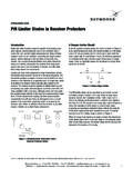
7 Cycle-to-cycle Jitter is used whenever there is a need to limit the size of a sudden jump in term peak-to-peak is defined as the difference between the smallest and the largest period sampled during JitterPeak-to-peak period Jitter is the difference between the largest clock period and the smallest clock period for all individual clock periods within an observation window, typically 1,000 or 10,000 cycles. It is a useful specification for guaranteeing the setup and hold time of flip flops in digital systems such as clock used for TIE Jitter and phase noiseCycle-to-Cycle Jitter (Jcc)Period Jitter (Jper)10 | Interval Error (TIE) Jitter or Phase JitterTIE Jitter , also known as accumulated Jitter or phase Jitter , is the actual deviation from the ideal clock period over all clock includes Jitter at all Jitter modulation frequencies and is commonly used in wide area network Timing applications, such as SONET, Synchronous Ethernet (SyncE) and optical transport networking (OTN).
8 More information on TIE and other Jitter types can be found in the Additional Resources Jitter (JTIE) | 11 Jitter Measurement UnitsDifferent measurements or statistics can be taken for all types of Jitter , although some are more common than type of Jitter is measured and specified in time increments of the clock error, usually pico-seconds or femto-seconds. A larger number generally indicates a lower performance Timing can also be specified in root mean square (RMS) of the Timing RMS values often assumes a Gaussian distribution and shows the standard deviation (1 ) of the Jitter CalculationTo calculate the RMS value for X where XRMS represents a discrete set of values (X1 .. Xn), use the formula below:12 | vs. Frequency Domain Jitter vs. Phase NoiseJitter is usually a time domain term, while phase noise is a frequency domain it is common for the terms to be used loosely with the result that they are often used theory and with perfect measuring equipment, phase noise measured to an infinite carrier offset would provide the same value as Jitter .
9 However, using practical test equipment there will always be a discrepancy between the , tools for each Measurement provide different views of the same phenomena, which are useful for seeing different types of Jitter and frequency is a time domain term Typically measured with an oscilloscope Directly measures peak-to-peak and cycle-to-cycle Jitter Time domain equipment generally has a higher noise floor than frequency domain equipmentPhase noise is a frequency domain term Typically measured with a spectrum analyzer in phase noise mode or a phase noise analyzer Cannot directly measure peak-to-peak or cycle-to-cycle Jitter Random Jitter vs. deterministic Jitter (spurs) are easily recognized spectrum analyzers and phase noise analyzers generally have lower noise floors than time domain equipment Can be integrated over different frequency bands to provide RMS phase | 13 Time vs.
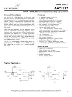
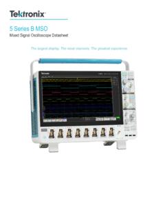
10 Frequency Domain Equipment Time Domain EquipmentTime domain equipment is typically a high-speed digitizing time domain equipment can measure all of the Jitter frequency components. It has the virtue of being able to directly measure peak-to-peak, cycle-to-cycle, period and TIE Jitter . This Measurement approach permits the Measurement of Jitter of very low frequency clock (or carrier) post-processing the data with various techniques such as FFTs and digital filters, it is possible to integrate the phase noise value over a specific band of frequencies to generate RMS phase Jitter domain equipment is very good at measuring data-dependent Jitter , which makes it very useful for high-speed serial links that use serializer/deserializer (SERDES) Domain Equipment Example: Keysight (Agilent) 90804 Digital Oscilloscope | Domain EquipmentFrequency domain equipment is usually a spectrum analyzer , a phase noise analyzer or a spectrum analyzer with phase noise Measurement domain equipment cannot directly measure peak-to-peak, cycle-to-cycle or period Jitter because its native capability is to measure the RMS power of signals in a given frequency band.