Transcription of TIMKEN SEAL SPECIFICSEAL SPECIFICATION …
1 SSGTHE TIMKEN COMPANYTHE TIMKEN COMPANYSEAL SPECIFICATION GUIDEWORLDWIDE LEADER IN BEARINGS AND STEEL 2001 The TIMKEN CompanyPrinted In the Order No. 7533 TIMKEN is the registered trademark ofThe TIMKEN Bath SealsKWIK-Sleeves - ComponentsSeal KitsO-RingsTIMKENA LEADER IN seal TECHNOLOGYUS $10 seal SPECIFICATION GUIDESEAL SPECIFICATION GUIDEHOW TO USE THIS CATALOGThe seals listed in this catalog are arranged by shaft size and part number. Determine the method you will use for yoursearch, then turn to the corresponding section found in thetable of contents. Each seal will have the dimensions, alongwith the seal type and material. If a specific seal is not found,contact your TIMKEN sales representative to check the availability of that particular data presented here is to provide a guideline or refer-ence for general information only, it is not intended to beused for engineering purposes.
2 Therefore, when installingany parts referenced in this catalog always follow the originalequipment manufacturer s instruction manual, specificationsand guidelines. The information referenced is deemed reliablebut not guaranteed. The TIMKEN Corporation reserves theright to make changes to, and amendments of, any informa-tion displayed. The TIMKEN Corporation also reserves theright to make any functional substitutions in type, style ordesign where deemed TIMKEN Company, known for its top-quality line of bear-ings, has extended its product line to include seals. TIMKEN ,with 77 seal patents, already had the product knowledge forseal design. In fact, it was only natural for TIMKEN to extendthis experience into a complete line of seals for the automo-tive aftermarket. Each and every seal sold by TIMKEN is man-ufactured with the same quality that goes into every Timkenbearing.
3 To help our customers in seal selection, we havedeveloped this seal SPECIFICATION Guide. If you have com-ments or suggestions on the seal SPECIFICATION Guide,please complete the postage paid card found in the back ofthis publication or send an e-mail to GUIDELINESThe data provided here is a guideline for theselection of a seal for a general or specificapplication. The user needs to be aware thatmany seal design configurations exist tomeet specific requirements. Therefore, firstlook-up the correct seal in the Bearing andSeal Application Catalog for Automotive andLight Truck, published by The TimkenCorporation. If you do not find the informationregarding the seal required:1. Determine the general category the seal application falls Determine if operating conditions exceed the design Shaft Speedb. Pressurec.
4 Eccentricity3. Select appropriate lip, case and is based on temperature ofapplication, fluid and environment to besealed or Review bore and shaft configurations to ensure compatibility with If any questions or concerns remain, contact your TIMKEN sales representativefor more information or maintenance and handling prac-tices are critical. Follow the equipmentmanufacturer s installation to follow installation instructionsand to maintain proper lubrication canresult in equipment failure and could leadto a risk of serious bodily SPECIFICATION GUIDE 2001 The TIMKEN CorporationPortions of this book are 2000 Freudenberg-NOK and reprinted with permission1 TABLE OF CONTENTSSECTION.. PAG Front CoverHow to Use This Front CoverGeneral Front CoverWarning ..Inside Front CoverSeal Nomenclature ..2 seal Design , Inside Back CoverShaft Recommendations.
5 7 Operating Conditions ..8-9 seal Selection ..11 seal Installation .. - Component ..15 Conversion Chart ..16 Size Section Seals Section V-Seals ..77-84 Size Section Oil Bath Section Section seal Kits ..94-97 Numeric Section Seals-Inch ..98-144 Numeric Section Seals-Metric ..145-150 Numeric Section V-Seals ..151-158 Numeric Section Oil Bath Seals ..159-161 Numeric Section KWIK-Sleeves ..162-167 Numeric Section seal Kits ..168-171 Metric Size ..172-183 Metric Part .. NOMENCLATURE1. seal Width2. Metal Case (Outer)3. Housing4. Inner Case5. Outside Face6. Lip Length7. Inside Face8. Radial Wall Dimension9. seal Outer Diameter10. Housing Bore Diameter11. Spring Position (R-Value)12. Spring Groove13. Garter Spring14. Axial Clearance15. Heel Section16.
6 Flex Section17. Spring Retainer Lip18. Head Section19. Inside Lip Angle20. Toe Face21. Inside Case Inner Diameter22. Outer Case Inner Diameter23. Auxiliary (Dust) Lip24. Outside Lip Surface25. Outside Lip Angle26. Rib (Helix)27. Contact Point28. Static Lip29. Inside Lip Surface30. Molded Toe Angle31. Spring Set Lip Diameter32. Free Lip (Unsprung) Diameter33. Contact Line Height34. Lip Height35. Lip Angle3 seal DESIGN/TYPES 10S20S50S40S80S90S70S2102402502603003102 9032033034035040041036043044045046048049 0470510520540560570590610650660680690700 620640740750760780710720 METALRUBBERFELTKEYTEFLONLEATHERSEAL SPECIFICATION GUIDESEAL DESIGN TYPES (continued) to to to to to to to to . to . to . to . to . to.
7 To .196 SHAFT RECOMMENDATIONSS haftsSeal and shaft compatibility is dependent on four conditions:shaft tolerance, lead-in chamfer, finish and hardness. Properconsideration of these conditions will assist in providing optimal seal performance. SHAFT HARDNESSis an important factor to preventexcessive wear, deformation, scratches or nicks, and toallow for easy machining for proper roughness. Under normal conditions, the seal contact area of the shaft should be Rockwell C45 minimum. SHAFT SURFACE ROUGHNESSis very important as thisgreatly influences the amount of lip wear. The recommend-ed roughness is as follows: Rotating 10 to 20 inch Ra (.25 M to .50 M Ra):RMAX=31-126 inch ( M) Reciprocating 5 to 10 inch Ra (.13 M to .25 MRa)The method of achieving this finish should not beoverlooked. PLUNGE GRINDINGis recommended for rotating shaftapplications.
8 For reciprocating applications, centerlessgrinding is acceptable. Rotating shaft applications require asurface with no machine lead, as machine lead may actu-ally pump fluid from under the seal lip. Also, hard chromeplating is suggested for any cast iron or stainless steelshafts for rotating applications and for steel shafts withreciprocating applications. A SHAFT CHAMFERis suggested to assist in the installa-tion process. Without a proper chamfer, the seal lip may bedamaged or distorted resulting in a dislodged garterspring. SHAFT TOLERANCE recommendations for general applications are listed below. The tolerance range shouldbe decreased for high speed or pressure -25 FreeEdgeRecommended Shaft ToleranceSHAFT DIAMETER (INCH) TOLERANCE SHAFT DIAMETER (DIN/METRIC) TOLERANCEUp to .003Up to 100 mm to.
9 To to . to Shaft ChamferSEAL SPECIFICATION GUIDE6 METAL inch Ra150 inch M M Ra492 inch M RMAXHOUSING RECOMMENDATIONSH ousingSteel and cast iron provide good surfaces for both rubber covered and metal seals. For soft alloy (aluminum)bores, rubber covered seals provide better sealing capability. In aluminum or other soft alloy bores, metal occasionally back out of the bore due to thermal expan-sion of the soft alloy. Rubber, having a higher coefficient ofthermal expansion than carbon steel, will tighten in the boresas temperature or nylon are not recommended because they typicallyexpand at a high rate causing a major problem for metal If plastic is to be used, rubber seals are ChamferA bore chamfer is necessary to assist in installation of theseal. To the right is the recommended configuration for chamfer angle and depth minimizes cocking or lack of squareness of the seal to the shaft, distortion of the sealcases, and reduces assembly RoughnessExcessively rough bore finishes may allow paths for fluid to leak between seal and bore.
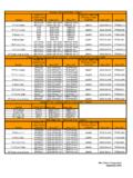
10 Below shows the recommended maximum rubber seal is capable of functioning with a Max. corner mustbe burr freeRecommended Bore ChamferMAXIMUMROUGHNESSA minimum bore roughness is recommended for rubber This improves inch M RaMINIMUMROUGHNESS7 BORE RECOMMENDATIONSNORMAL PRESS TOLERANCE (1)OUT OF ROUND (2)BOREBORESEALS WITHSEALS WITHSEALS WITHSEALS WITHSEALS WITHSEALS WITHDIAMETERTOLERANCEMETAL to ..002 . - ..002 . - ..002 . - ..002 . - . +.003 .. - . +.. - . +.. - . +..002 Bore Diameter ToleranceThe recommended housing bore diameter, bore tolerance and nominal SIZESEQUIVALENT METRIC SIZES(1) seal - The average of a minimum three measurements to betaken at equally spaced positions.(2) Out of Round (OOR) - The maximum variance between any of thereadings used in determining seal PRESS TOLERANCE (1)OUT OF ROUND (2)BOREBORESEALS WITHSEALS WITHSEALS WITHSEALS WITHSEALS WITHSEALS WITHDIAMETERTOLERANCEMETAL to - - - - + - + - + - + SPECIFICATION GUIDE8 OPERATING CONDITIONSNOTE: Higher shaft speed is possible using higher temperature materials such as polyacrylate, fluoroelastomeror silicone.