Transcription of Title: Automatic Securing Mechanism / Lock Module ...
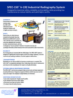
1 Title: Automatic Securing Mechanism / Lock Module Replacement Procedures Source Production & Equipment Company, Inc. 113 Teal Street, St. Rose, LA 70087 Form No. PR01F5 Revision Date: 06/02/04 Revision (1) Page 1 of 3 ASM Lock Module Replacement MODEL SPEC-150 RADIOGRAPHY EXPOSURE DEVICE Automatic Securing Mechanism / Lock Module Replacement Procedures NOTICE ** Although the SPEC-150 Exposure Device is designed to operate reliably without lubrication, users may use lubrication that is suitable for the operating environment. If lubrication is used, users should consider the need to perform maintenance to remove and / or replace the lubrication if significant changes in environment are encountered. ** Do not replace the tamper resistant bolts or screws with any other type of fastener.
2 The SPEC-150 Exposure Device is licensed as a Type B(U) container and modifications are prohibited. ** Notify your Radiation Safety Officer and SPEC immediately if the replacement Module does not operate properly. ** ASM / Lock Module The ASM / Lock Module Assembly contains the exposure device lock, the source assembly lock, and the Automatic Securing Mechanism . It is removed from the exposure device only with the use of special tools provided by SPEC. The ASM / Lock Module contains no user serviceable parts. It must be returned to SPEC ro other authorized licensee for maintenance and repair controlled by an NRC approved QA program. These instructions must be read completely prior to performing any of the ASM / Lock Module replacement steps. Following the proper sequence of steps will ensure correct installation and prevent problems (such as misalignment) during the replacement procedure.
3 Special Tools (provided by SPEC) Hand Number 150011-3 Torx Tip and Number 150011-7 Special Allen Number 150011-11 Dummy Source Number 151216-1 Dummy Number 150010-1 ASM / Lock Module Removal 1. Transfer the source assembly from the exposure device to a C-1 source changer or other storage container. A calibrated and properly operating survey meter must be used during all source transfers in accordance with the company s operating procedures. 2. With the control assembly attached to the exposure device and the drive cable extended through the changer tube (guide tube), connect the drive cable to the dummy connector (not the dummy source assembly) provided with the special tools. (See attached drawing for dummy connector and dummy source assembly illustrations). 3. Crank the dummy connector fully into the exposure device.
4 4. Lock the exposure device and remove the controls. (Note: The dummy connector will also pull out of the exposure device.) Title: Automatic Securing Mechanism / Lock Module Replacement Procedures Source Production & Equipment Company, Inc. 113 Teal Street, St. Rose, LA 70087 Form No. PR01F5 Revision Date: 06/02/04 Revision (1) Page 2 of 3 ASM Lock Module Replacement 5. Remove the dummy connector from the drive cable. (After the replacement Module is installed, the controls cannot be attached if the dummy connector is still in place.) 6. Using the hand driver, remove the six (6) screws from the ASM / Lock Module lid at the top of the exposure device. 7. Using the special allen wrench, remove the four (4) bolts from the lock end plate. (An alternate tool may be supplied to perform the lock Module change out.) 8. Push the exposure device lock inward while lifting the ASM / Lock Module through the top of the exposure device.
5 ASM / Lock Module Installation 1. Visually inspect the replacement ASM / Lock Module to verify that it is in the locked position, with the key slots in the exposure device lock vertical. (See lock orientation on attached drawing.) 2. Remove the four (4) bolts from the replacement Module . Protect the anti-seize compound (which is already applied to the bolt s threads) from dirt and other debris. 3. Insert the replacement lock Module into the exposure device. 4. Insert the device key into the device lock to align the lock Module . Note: Even minor misalignment may cause difficulty rotating the operating lever when attempting to unlock the source assembly. 5. Insert the four (4) bolts through the end plate. Hand tighten to protect against cross-threading. 6. Firmly tighten the four (4) bolts using the special allen wrench. 7.
6 Clean and install the six (6) Module lid screws into the top of the exposure device using the hand driver. 8. Install the controls (the dummy connector must be removed), unlock the exposure device lock, and unlock the source lock. Note: If the operating lever or exposure device lock is difficult to rotate, this is an indication that the lock Module was not properly aligned with the housing end plate. Loosen all ten (10) fasteners and repeat steps 4-7. 9. Crank the drive cable forward through the exposure device. 10. Attach the dummy source assembly to the drive cable connector and retract it to the fully secured position. 11. Perform the SPEC-150 Operation Check referenced in the SPEC-150 User s Manual to verify that the replacement Module was installed properly and that all exposure device functions are normal BEFORE installing the active source assembly.
7 Warranty: Replacement ASM / Lock Module Units are warranted to be free of defects in material and workmanship for a period of thirty (30) days from the date of shipment. Title: Automatic Securing Mechanism / Lock Module Replacement Procedures Source Production & Equipment Company, Inc. 113 Teal Street, St. Rose, LA 70087 Form No. PR01F5 Revision Date: 06/02/04 Revision (1) Page 3 of 3 ASM Lock Module Replacement