Transcription of TJERNLUND PRODUCTS, INC. - Duct and Dampers
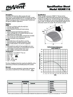
1 Copyright 2011, TJERNLUND Products, Inc. All rights 8504160 REV. A 3/11 RECOGNIZE THIS SYMBOL AS AN INDICATION OF IMPORTANT SAFETY INFORMATION!THESE INSTRUCTIONS ARE INTENDED AS AN AID TO QUALIFIED, LICENSED SERVICE PERSON-NEL FOR PROPER INSTALLATION, ADJUSTMENT AND OPERATION OF THIS UNIT. READ THESEINSTRUCTIONS THOROUGHLY BEFORE ATTEMPTING INSTALLATION OR OPERATION. FAILURETO FOLLOW THESE INSTRUCTIONS MAY RESULT IN IMPROPER INSTALLATION, ADJUSTMENT,SERVICE OR MAINTENANCE POSSIBLY RESULTING IN FIRE, ELECTRICAL SHOCK, CARBONMONOXIDE POISONING, EXPLOSION, PERSONAL INJURY OR PROPERTY DAMAGE. THIS INSTAL-LATION MANUAL DOES NOT CONTAIN ANY SYSTEM DESIGN DOCUMENTATION.!DO NOT DESTROY. PLEASE READ CAREFULLY AND KEEP INA SAFE PLACE ON JOB SITE FOR FUTURE & RT1500 For Gas & Oil ApplicationsRT750H & RT1500 HFor Solid Fuel ApplicationsRooftop InducersFOR NATURAL GAS, LP, OIL-FIRED,SOLID FUEL HEATING APPLIANCESAND GENERAL VENTILATIONTJERNLUND PRODUCTS, Ninth Street White Bear Lake, MN 55110-6794 PHONE (800) 255-4208 (651) 426-2993 FAX (651) 426-9547 Visit our web site Inducers are tested and Listed to ULStandard 378 for Draft EquipmentRated up to 1000 FRooftop Inducers are tested and Listed toANSI/UL 705-2004 Power VentilatorsRooftop Inducers are tested and Listed to CAN3-B255-M81 for Mechanical Flue-Gas ExhaustersRestricted to Non-Solid Fuel applications only under the scope of standard CAN3-B255-M81 Rated up to 575 F / 300 C in CanadaFor non-condensing applications only.
2 Not suitable for Side Wall :Use of this product could cause flues to reverse (back-draft) on other heating equipment with-in the same structure if adequate make-up air is not provided. Check for flue gas spillage of atmospheri-cally vented heaters after rooftop Inducer installation and always have working carbon monoxide detectorsinstalled per the CO detector manufacturer s instructions and local codes. Make-up / combustion air fansare available from TJERNLUND if OF CONTENTSPAGE(S)DESCRIPTION .. 1 DIMENSIONS AND SPECIFICATIONS .. 1 FAN PERFORMANCE RESTRICTIONS & CAUTIONS .. 3 INSTALLER RESTRICTIONS & CAUTIONS IN FRENCH CANADIAN .. 3-4 TERMINATION CLEARANCES FOR CANADIAN & INSTALLATIONS .. 4 INSTALLATION .. 5-7RT750 / RT1500 - PSA-1 FAN PROVING SWITCH INSTALLATION .. 7 WIRING OPTIONS ..8-11 SIZING A COMMON MANIFOLD SERVING MULTIPLE HEATERS ..12RT750 / RT1500 - PSA-1 SAFETY INTERLOCK AND DRAFT ADJUSTMENT SET-UP / RT1500H SPEED CONTROL ADJUSTMENT.
3 13-14 COMBUSTION AIR ..14 INSPECTION & MAINTENANCE ..14 TROUBLESHOOTING ..14 HOW TO OBTAIN SERVICE & LIMITED WARRANTY ..14-15 REPLACEMENT PARTS ..15 TJERNLUND Products welcomes your comments and questions. Call us at 800-255-4208, Fax 651-426-9547, Email us at or write to: Customer Service, TJERNLUND Products, Inc., 1601 Ninth Street, White Bear Lake, MN & RT1500 models are supplied with the model PSA-1 Fan Proving Switch which will disable the burner(s) if an Inducer mal-function should occur and are compatible with TJERNLUND UC1, UCRT and DCOP1 interlock controls. The RT750H & RT1500H aresupplied with a wall mount speed control to vary inducer performance in solid fuel applications. The Rooftop Inducer may be used onpositive or negative pressure rated chimneys because the fan creates a negative pressure throughout the entire venting for use on natural gas, LP-gas, oil-fired, solid fuel heating systems or general ventilation. Also applicable for dryers, gas fire-places, stoves, BBQ s or pizza ovens.
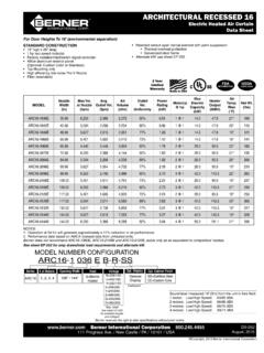
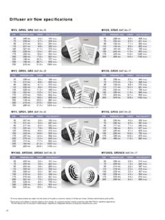
4 The Rooftop Inducer must always be installed outdoors at the vent system termination. Refer toheating appliance manufacturer's instructions regarding specific venting SELECTION INFORMATIONS election of a Rooftop Inducer involves determination of the maximum volume of air or gases to be handled, their density and themaximum static pressure which the fan must overcome. Rooftop Inducer performance needs to be de-rated from 70OF performancecurves to anticipated air or gas temperatures. Please feel free to contact us for application and model selection assistance by calling800-255-4208 or email us at Vent layout or other information can be faxed to 651-426-9547. See Sizing aCommon Manifold Serving Multiple Heaters on Page 12 for manifold AND 15/167 15/1614 1 3/442518 1/247028611 1 3/447hpMODELV oltageRPMAmpsPower Rating120 1/257244517 1/2( )inletDEFBCAROOFTOP INDUCER SELECTION TABLES2002004006008001000 CFM (STD. AIR 70 DEGREES F)STATIC PRESSURE (INCHES )0RT12 (120 VAC)MINIMUM SPEEDWITH TJERNLUNDSPEED CONTROLMODELS RT1500 & RT1500 HOPERATINGRANGEMAXIMUM SPEEDWITH TJERNLUNDSPEED SERIESMODELS RT750 & RT750 HOPERATINGRANGE(120 VAC)MAXIMUM SPEEDMINIMUM SPEEDWITH TJERNLUNDSPEED CONTROLWITH TJERNLUNDSPEED CONTROL00100200300400500 CFM (STD.)
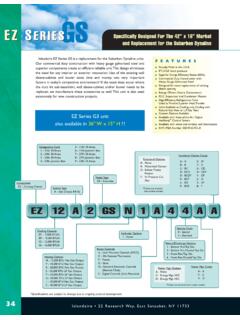
5 AIR 70 DEGREES F)STATIC PRESSURE (INCHES ) RT750 & RT750H MODELS RT1500 & RT1500H *IMPORTANT:Select the inducer based on the BTU/hr input of the appliance(s) rather thanthe diameter of the appliance(s) vent outlet or chimney. Vent/Chimney sizes listed are thesmallest inside diameter recommended for the associated BTU/hr input. Use a tapered reduc-ing collar or transition fitting if the vent is reduced to the pipe diameter listed in selection determine equivalent feet, add the total length of straight vent pipe plus 10 feet for each 90degree elbow and 5 feet for each 45 degree elbow. ROOFTOP INDUCER FAN CURVESM odels RT750 & RT1500 SelectionTable for Gas & Oil ApplicationsModels RT750H & RT1500H Selection for Solid Fuel FireplacesEfficient draft that moves smoke up the chimney andkeeps it from entering the living area is dependent onmaintaining a negative pressure capture velocity at thehearth opening. Even if glass fireplace doors are present,reducing the open area, a negative pressure capturevelocity must be calculated based on the entire hearthopening since the doors need to be opened to add addi-tional the vertical and horizontal hearth opening todetermine the face area opening in square feet.
6 If thefireplace is open on the sides or back total all openingsto arrive at the total face typically the fire can be maintained but smoke drifts intothe room, select the model which has a face area capaci-ty equal or greater than the face Face Area:RT750H 14 Ft RT1500H28 Ft TJERNLUND offers free design recommendations for unusu-al fireplace designs, such as free-standing and customgas fireplaces. If in doubt, consult RESTRICTIONSF ailure to install, maintain and/or operate the Rooftop Inducer in accordance with manufacturer's instructions may result in conditionswhich can produce bodily injury and property Rooftop Inducer must be installed by a qualified installer in accordance with these instructions and all local codes or in theirabsence in accordance with the latest edition of The National Fuel Gas Code (NFPA 54), NFPA 211 or 31 when applicable, the latestedition of the National Electrical Code (NFPA 70) and the Occupational Safety and Health Act (OSHA) when applicable.
7 In theabsence of local codes in Canada, installations must comply with the Canadian Electrical Code (CSA Std ), the latest edition ofthe Natural Gas Installation Code ( ), the Propane Installation Code ( ) and the Installation Code forOil Burning Equipment (CSA Std B139-M91).Improper installation can create a hazardous condition such as an explosion, fire, electrical shock or carbon monoxide poisoningresulting in property damage, personal injury or The Rooftop Inducer may be installed on natural gas, LP-gas, oil-fired, solid fuel heating systems or general ventilation systems. The Rooftop Inducer is not suitable for use on condensing The Rooftop Inducer was tested with exit flue gas temperatures of 1000OF (537OC) and 575OF (300OC) The Rooftop Inducer may not be installed on incinerators or incinerating The Rooftop Inducer must always be installed at the vent system termination. Not suitable for Side Wall The Rooftop Inducer shall not be installed on an appliance with an automatic valve having a manual opener unless the manual opener has been rendered inoperative or the automatic valve has been replaced with a valve not equipped with a manual RT750 / RT1500 Rooftop Inducers may only be installed on appliances equipped with a draft hood, draft diverter, barometric draft control or other dilution air providing Rooftop Inducer is designed to fit any type of nominal (8" Models RT750 / RT750H) or (12" Models RT1500 / RT1500H) diame-ter vent pipe.
8 Vent pipe must be installed and supported according to manufacturer's instructions and/or in accordance with NFPA211,"Chimneys and Vents". Factory insulated vent pipe may reduce clearances to combustibles when penetrating a combustible to vent pipe manufacturer's instructions for CAUTIONSD isconnect the power supply when making wiring connections or when working around the Inducer impeller and motor. Failure to doso can result in electrical shock, personal injury, death or property The model PSA-1 Fan Proving Switch provided must be interlocked with the heating appliance burner(s).2. Plan the vent system so that the code required clearances are maintained from plumbing, wiring and Make certain the power supply is adequate for Rooftop Inducer motor requirements. Do not add the Rooftop Inducer to a circuit where the total load is The installer must verify that the appliance(s) on which the Rooftop Inducer will be installed is in a safe operating condition.
9 Consultappliance manufacturer's Instructions for Rooftop Inducer housing is single wall. Standard clearances to combustibles must be D'INSTALLATIONNe pas installer, entretenir et(ou) utiliser le Syst me d'admission d'air pour toit conform ment aux directives du fabricant pourraitentra ner des circonstances qui causeront des blessures et endommageront la propri t .Le Syst me d'admission d'air pour toit doit tre install par un installateur qualifi conform ment aux pr sentes directives et toutesles normes applicables la localit . En l'absence de normes locales au Canada, les installations doivent respecter le Code canadiende l' lectricit (CSA Std ), la derni re version du Code d'installation du gaz naturel ( ), le Code d'installation dupropane ( ) et le Code d'installation des appareils de combustion au mazout (CSA Std B139-M91).Une installation inad quate pourrait entra ner un danger, comme une explosion, un feu, une d charge lectrique ou un empoison-nement au monoxyde de carbone qui endommagera la propri t , occasionnera des blessures ou m me la Le Syst me d'admission d'air pour toit peut tre install sur des syst mes de chauffage aux gaz naturels, aux gaz de p troles liqu fi s, au mazout ou aux combustibles solides ou syst mes de ventilation g n rale.
10 Le Syst me d'admission d'air pour toit ne convient pas aux syst mes de Le Syst me d'admission d'air pour toit a t test des temp ratures des gaz la sortie du conduit de 575 F (300 C) Le Syst me d'admission d'air pour toit ne doit pas tre install sur des incin rateurs, des cuvettes sanitaires incin ration ou des appareils br lant un combustible Le Syst me d'admission d'air pour toit doit toujours tre install l'extr mit du syst me de ventilation. Il ne doit tre mont qu'en pla ant l'arbre de moteur la Le Syst me d'admission d'air pour toit ne doit pas tre install sur un appareil quip d'une valve automatique ayant un dispositif d'ouverture manuel, moins que le dispositif d'ouverture manuel ne fonctionne plus ou que la valve automatique a t remplac e par une valve sans dispositif d'ouverture Les mod les RT750 / RT1500 du Syst me d'admission d'air pour toit ne peuvent tre install s que sur les appareils quip s d'un coupe-tirage, d'une hotte de tirage, du r glage barom trique du tirage ou toute autre source de ventilation de Syst me d'admission d'air pour toit est con u pour tout tuyau de ventilation d'un diam tre nominal de (8" Mod les RT750 /RT750H) ou (12" Mod les RT1500 / RT1500H).