Transcription of TL712 DIFFERENTIAL COMPARATOR - Brandeis …
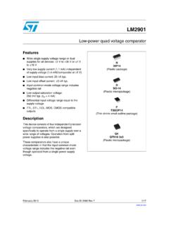
1 TL712 . DIFFERENTIAL COMPARATOR . SLCS002C JUNE 1983 REVISED AUGUST 2000. D Operates From a Single 5-V Supply D, P, OR PS PACKAGE. D 0 to V Common-Mode Input Voltage (TOP VIEW). Range D Self-Biased Inputs NC. IN . 1. 2. 8. 7. VCC. OUT . D Complementary 3-State Outputs IN+ 3 6 OUT+. D Enable Capability OE 4 5 GND. D Hysteresis .. 5 mV Typ D Response Times .. 25 ns Typ NC No internal connection description The TL712 is a high-speed COMPARATOR fabricated with bipolar Schottky process technology. The circuit has DIFFERENTIAL analog inputs and complementary 3-state TTL-compatible logic outputs with symmetrical switching characteristics.
2 When the output enable (OE) is low, both outputs are in the high-impedance state. This device operates from a single 5-V supply and is useful as a disk memory read-chain data COMPARATOR . The TL712C is characterized for operation from 0 C to 70 C. AVAILABLE OPTIONS. PACKAGED DEVICES. TA PLASTIC PLASTIC. PLASTIC DIP. SMALL OUTLINE SMALL-OUTLINE EIAJ. (P). (D) (PS). 0 C to 70 C TL712CD TL712 CPSR TL712CP. The PS package is only availiable tape and reeled. The D package also is available taped and reeled. Add the suffix R to device type ( , TL712 CDR).
3 Symbol (positive logic). 4. OE. 2 7. IN OUT . 3 6. IN+ OUT+. PRODUCTION DATA information is current as of publication date. Copyright 2000, Texas Instruments Incorporated Products conform to specifications per the terms of Texas Instruments standard warranty. Production processing does not necessarily include testing of all parameters. POST OFFICE BOX 655303 DALLAS, TEXAS 75265 1. TL712 . DIFFERENTIAL COMPARATOR . SLCS002C JUNE 1983 REVISED AUGUST 2000. schematics of inputs and outputs EQUIVALENT OF EACH EQUIVALENT OF EACH ENABLE INPUT TYPICAL OF ALL OUTPUTS.
4 DIFFERENTIAL INPUT. VCC VCC. VCC 85 . k Nom Nom 4 k 960 . Nom Nom Input OE. 960 . Nom Output absolute maximum ratings over operating free-air temperature range (unless otherwise noted) . Supply voltage, VCC (see Note 1) .. 7 V. DIFFERENTIAL input voltage, VID (see Note 2) .. 25 V. Input voltage, VI, any DIFFERENTIAL input .. 25 V. Output enable voltage .. 7 V. Low-level output current, IOL .. 50 mA. Package thermal impedance, JA (see Note 3): D package .. 97 C/W. P package .. 85 C/W. PS package .. 95 C/W. Lead temperature 1,6 mm (1/16 inch) from case for 10 seconds.
5 260 C. Storage temperature range, Tstg .. 65 C to 150 C. Stresses beyond those listed under absolute maximum ratings may cause permanent damage to the device. These are stress ratings only, and functional operation of the device at these or any other conditions beyond those indicated in the recommended operating conditions section of this specification is not implied. Exposure to absolute-maximum-rated conditions for extended periods may affect device reliability. NOTES: 1. All voltage values, except DIFFERENTIAL voltages, are with respect to the network ground.
6 2. DIFFERENTIAL voltage values are at IN+ with respect to IN . 3. The package thermal impedance is calculated in accordance with JESD 51. 2 POST OFFICE BOX 655303 DALLAS, TEXAS 75265. TL712 . DIFFERENTIAL COMPARATOR . SLCS002C JUNE 1983 REVISED AUGUST 2000. recommended operating conditions MIN NOM MAX UNIT. Supply voltage, VCC 5 V. Common-mode input voltage, VIC 0 V. High-level output current, IOH 1 mA. Low-level output current, IOL 16 mA. Operating free-air temperature, TA 0 70 C. electrical characteristics at VCC = 5 V, TA = 25 C.
7 PARAMETER TEST CONDITIONS MIN TYP MAX UNIT. VT Threshold voltage (VT + and VT ) VICR = 0 to 5 V 100 100 mV. Vhys Hysteresis (VT + VT ) 5 mV. VOH High-level output voltage VID = 100 mV, IOH = 1 mA V. VOL Low-level output voltage VID = 100 mV, IOL = 16 mA V. IOZ Off-state output current VO = V 20 A. II Enable current VI = V 100 A. IIH High-level enable current VIH = V 20 A. IIL Low-level enable current VIL = V 360 A. ri DIFFERENTIAL input resistance 4 k . ro Output resistance 100 W. IOS Short-circuit output current 15 85 mA.
8 ICC Supply current VID = 0, No load 17 20 mA. The algebraic convention, where the more negative limit is designated as minimum, is used in this data sheet for input threshold voltage levels only. switching characteristics, VCC = 5 V, TA = 25 C. PARAMETER TEST CONDITIONS MIN TYP MAX UNIT. tPLH Propagation delay time, low-to-high-level output 25 ns TTL load, load See Figure 1. 1, See Note 4. tPHL Propagation delay time, high-to-low-level output 25 ns NOTE 4: The response time specified is for a 100-mV input step with 5-mV overdrive (105 mV total), and is the interval between the input step function and the instant when the output crosses V.
9 POST OFFICE BOX 655303 DALLAS, TEXAS 75265 3. TL712 . DIFFERENTIAL COMPARATOR . SLCS002C JUNE 1983 REVISED AUGUST 2000. PARAMETER MEASUREMENT INFORMATION. 5V. 2 k . Output NOTE A: All diodes are 1N4148 or equivalent. Figure 1. TTL Output Load Circuit TYPICAL CHARACTERISTICS. OUTPUT RESPONSE FOR VARIOUS OUTPUT RESPONSE FOR VARIOUS. INPUT OVERDRIVE VOLTAGES INPUT OVERDRIVE VOLTAGES. VCC = 5 V VCC = 5 V. Input Voltage Input Voltage DIFFERENTIAL DIFFERENTIAL TTL Load TTL Load TA = 25 C TA = 25 C. 100 mV + Overdrive 100 mV + Overdrive VO Output Voltage V.
10 VO Output Voltage V. 5 5. 100 mV. 4 50 mV 4 100 mV. 20 mV 50 mV. 3 3 5 mV. 5 mV 20 mV. 2 2. 1 1. 0 0. 0 5 10 15 20 25 30 35 40 0 5 10 15 20 25 30 35 40. t Time ns t Time ns Figure 2 Figure 3. 4 POST OFFICE BOX 655303 DALLAS, TEXAS 75265. TL712 . DIFFERENTIAL COMPARATOR . SLCS002C JUNE 1983 REVISED AUGUST 2000. TYPICAL CHARACTERISTICS. COMMON-MODE. PULSE RESPONSE. VIC Common-Mode 4. Input Voltage 3 VCC = 5 V. TA = 25 C. 2. 1. 0 50 . VO. VO Output Voltage V. 50 . VIC. 0 20 40 60 80 100 120 140 160. t Time ns Figure 4.