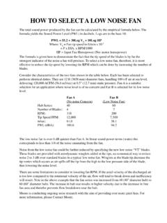
Transcription of TMC 661 - Moore Fans
1 800 S. MISSOURI AVENUE MARCELINE, MISSOURI 64658-1602 PHONE (660) 376-3575 FAX (660) 376-2909 E-MAIL Flow2 Hub Size and Effect3 Blade Section3 Pitch and Blade Angle3 Blade Angle and Width for Aerodynamic Design 4 Blade Plan Form5 Number of Blades6 Blade Speed and RPM6 Limitations of Fan Wheels6 Deflection of Discharge7 CONTENTSFAN DESIGNTMC-661-Rev B12/012 TMC-661-Rev - B -12/01 CLUniform Velocity fromhub to tipOne of the most important designconsiderations in a fan wheel is that itmust impart to the air stream a uniformvelocity and pressure over its CONSIDERATIONS INFAN DESIGNThe following discussion describes the basic considerations inefficient axial flow fan design and illustrates features that willassist the reader in recognizing well-designed FLOWOne of the most important requirements of a fan wheelis that it must impart to the air stream a uniform velocityand pressure over its entire area. Any well-designed fanwheel is sure to have two characteristics:1.
2 The individual blades will be narrow at the tip,where the blade velocity is high, and will widen toward thehub, where more blade area is required due to lower The angle of the blades to the plane of rotation willbe minimum at the tip and increase as the hub is ap-proached. Only with such calculated width and angle foreach point on the blade can the design considerations ofuniform velocity and pressure be necessity for uniform flow and pressure is easilyexplained: If certain portions of the blade are not able todevelop the pressure necessarily being carried by otherportions of the blade, back flow of air at these points willoccur. Such would be the case in the vicinity of the hub ifa typical airplane propeller were adapted as a axial discharge velocities will waste power in excessvelocity pressure. Since velocity pressure increases as thesquare of the velocity, unequal discharge velocities, whenconverted into velocity pressure, will average out to ahigher overall velocity pressure than if the velocity wereuniform over the discharge area.
3 For this reason, fanswhich develop the greater part of their velocity and pres-sure near the blade tip will invariably fall short whenefficiencies are considered. For example, a fan of 80% efficiency with a uniformdischarge velocity of 2000 FPM ( m/sec) would have avelocity pressure of " ( mm). Assume another fan inwhich 1/2 of the air volume being handled left the blower at1000 FPM ( m/sec) while the other half left at 3000 FPM( m/sec). The velocity pressure of the first half wouldbe " ( mm), while the velocity pressure of the secondhalf would rise to " ( mm), making the work done onthe air, neglecting the static pressure, the equivalent of theaverage of the two, or " ( mm) velocity this unit handling air at zero static pressure, itsefficiency would be .25/.31 of the efficiency of the unitwith uniform flow, or about 65% as compared to 80% forthe fan with uniform - B -12/01 HUB SIZE AND EFFECTThe question of how large a fan hub should be is commonlyasked.
4 The answer is simple: A hub must be large enough to pick upwhere the blades are no longer able to carry the load. As the radiusis reduced and the center of the fan approached, the reduction in thespeed of the blade section reduces the potential work which may beaccomplished by the blade and increases the mean blade width will begin to increase abnormally and the blade anglewill rise sharply until additional width and angle are no longerpractical. At this point the hub must hub serves two major (aerodynamic) purposes. It allowstermination of the blades at a point where they would cease tofunction efficiently and it prevents back flow of air through the hub is too large for the required performance, the result willbe an increase in velocity pressure, due to the smaller net opening,and subsequent waste of power. If the hub is too small for therequired performance, the result will be deterioration of the flownear the hub, possibly even a reversal of flow in this to the drawing on the following page will readilyshow the necessity of a hub of some proportion.
5 As the centerline ofthe wheel is approached, the width of the blade becomes infinite. Forpractical reasons, it is evident that the hub in this example shouldstart at or near the "RADIUS = 2" point to avoid excessive fan hub must, of course, also serve a structural function inconnecting the blades and imparting rotation to them. The hub sizerequired by the aerodynamic considerations discussed in the pre-ceding paragraphs would result in an extremely heavy (and expen-sive) structural member. For this reason, fan manufacturers usuallyprovide a hub that is inadequate from an aerodynamic point of solves this problem by providing two hub designs for eachseries of fan: A smaller structural hub and a properly proportionedaerodynamic hub referred to as the Air SECTIONThe airfoil shape of the fan blade should be selected on the basisof high efficiency -- that is, high lift and low drag -- as well as the liftcoefficient desirable in the particular instance.
6 The abruptness atwhich stalling occurs should also be considered. Fortunately, exten-sive studies have been made on the performance of thousands ofshapes of airfoils. This information is readily available and fur-nishes complete performance data on each section, considering lift,drag, angle of attack, and other test data. Such information isinvaluable to the fan designer since these known characteristicsenable him to predict accurately the performance of the wheel AND BLADE ANGLEThe term pitch is defined as the advance of the air stream perrevolution of the fan wheel. Pitch may be expressed in feet perrevolution but, for convenience and in order to make it a dimension-less quantity, pitch will be referred to here in terms of hub example, a fan with an (aerodynamic) hub diameter of 4 feet,operating at a pitch of 2 hub diameters, would be moving air axiallythrough the wheel at a rate of 8 feet per revolution of the angle, or blade setting, is not to be confused with angle denotes the angle of the blade with the plane of rotationat a given point on the blade.
7 It is important to note that, for uniformflow and constant pitch, every point on the blade, fromMoore avoids compromising on hubsize by providing twohubs! Each properly proportionedfor its HubStructural HubThe vector diagrams above show the relative velocity of the blade and the air, taken at the sectionsindicated. The vertical vectors represent air velocity at each radius and are equal as required by efficientdesign. The horizontal vectors represent the speed of the blade at each radius and decrease from tip tocenter. The resultant vectors represent the blade angle and resultant velocity of the blade at each radiusfor a blade which is only free wheeling and performing no work on the air ELEVATION - BLADE APPROACHINGThe drawing above represents a front elevation of a blade blowing upward, rotating towardthe observer about the center line of the driving shaft, shown at left. The leading edge isassumed to be straight and the increase in required width as the center is approached istaken up by the trailing DIAGRAMSCROSS SECTION OF BLADE SHOWING BLADE ANGLEThe blade sections above portray to scale the blade angle at each radius required to permit unobstructedair flow, based upon the assumption of free wheeling.
8 Some increase in angle at the tip and aconsiderable increase near the center would be necessary if the blade were to exert work upon the movingair stream. These blade sections also show the width required at each radius to develop an equalpressure on the air stream from the tip ANGLE AND WIDTH FOR AERODYNAMIC DESIGN45 TMC-661-Rev - B -12/01 AerodynamicBlade DesignThe drawing above representsequidistant profiles of an end view ofthe blade. Note that from the thin,narrow tip to the thick, camberedroot, each blade has, at design pitch,the proper combination of airfoilcamber, width and angle to provideuniform pressure and velocity fromthe hub to the tip. This is thecriterion of efficient axial flow blades (which must, ofnecessity, be of uniform width) cannotmatch the efficiency of blades that areproperly of 4 ft ( m), operating at a pitch of 2 hub diameters, would bemoving air axially through the wheel at a rate of 8 feet ( m) per revolutionof the angle, or blade setting, is not to be confused with pitch.
9 Bladeangle denotes the angle of the blade with the plane of rotation at a givenpoint on the blade. It is important to note that, for uniform flow andconstant pitch, every point on the blade, from the hub to the tip, must havea different we assume a condition in which a wheel is operating at a given speedwith air being forced through the wheel at a given velocity, and the wheelitself exerting no work on the air stream, the blade angles at various pointson the blade will be approximately as illustrated on the preceding this chart, V represents the velocity of the air, which is constantover the entire blade length. The letter U represents the relativedirection between the blade and air preceding discussion, as well as the illustration, is based on theblade merely free-wheeling in the air stream, neither assisting or retardingthe air flow. In order for the blades to produce work, an additional anglemust be provided. This is called the angle of attack, generally from twoto six degrees, and is additive to the relative angle described above.
10 Inaddition, another angle also must be added to each section of the bladeto compensate for the deflection imposed upon the air stream by thewheel. As the air is deflected in passing through the wheel, 1/2 of the totaldeflection angle at each radius of the blade must be added to the anglealready obtained. Since the deflection is greater nearer the hub, an addedangle which may be as great as 25 degrees in itself would be required atthe hub, while only a minimum increase of 5 or 10 degrees in angle wouldbe made at the tip. This results in a great deal of twist in a properlydesigned we assume a fixed velocity through the wheel, an increase of two orthree degrees would probably be sufficient to cause stalling and abreakdown of flow. In actual operation, increasing the angle of the bladewould increase the air flow to a limited extent and stalling would probablynot occur as readily as in the previous example. See Section 4, "Opera-tion" in the Owner's Manual for a detailed discussion of the effects ofincreasing blade PLAN FORMA lthough the lift coefficients of different airfoil sections vary, it isnecessary that a fan for a given duty have a total blade width at each pointon the blade which is determined by the requirements of the angle of attackat the lift coefficient chosen.