Transcription of TMC5130A-TA DATASHEET
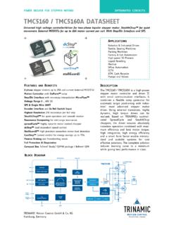
1 POWER DRIVER FOR STEPPER MOTORS INTEGRATED CIRCUITS. TMC5130A-TA DATASHEET . Universal high voltage controller/driver for two-phase bipolar stepper motor . StealthChop for quiet movement. Integrated MOSFETs for up to 2 A motor current per coil. With Step/Dir Interface and SPI. APPLICATIONS. Textile, Sewing Machines Lab & Factory Automation 3D Printers Liquid Handling Medical Office Automation CCTV, Security ATM, Cash recycler POS. Pumps and Valves Heliostat Controller FEATURES AND BENEFITS DESCRIPTION. 2-phase stepper motors up to 2A coil current ( peak) The tmc5130a is a high-performance Motion Controller with sixPoint ramp stepper motor controller and driver IC.
2 Step/Dir Interface with microstep interpolation MicroPlyer with serial communication interfaces. It Voltage Range 46V DC combines a flexible ramp generator for automatic target positioning with SPI & Single Wire UART. industries' most advanced stepper motor Encoder Interface and 2x Input driver. Based on TRINAMICs sophisticated Highest Resolution 256 microsteps per full step StealthChop chopper, the driver ensures StealthChop for extremely quiet operation and smooth motion absolutely noiseless operation combined SpreadCycle highly dynamic motor control chopper with maximum efficiency and best motor DcStep load dependent speed control torque.
3 High integration, high energy StallGuard2 high precision sensorless motor load detection efficiency and a small form factor enable miniaturized and scalable systems for CoolStep current control for energy savings up to 75%. cost effective solutions. The complete Integrated Current Sense Option solution reduces learning curve to a Passive Braking and freewheeling mode minimum while giving best performance Full Protection & Diagnostics in class. For higher currents, use the Compact Size 9x9mm2 TQFP48 package register compatible TMC5160 driver IC. BLOCK DIAGRAM. TRINAMIC Motion Control GmbH & Co. KG. Hamburg, Germany tmc5130a DATASHEET (Rev.)
4 / 2019-NOV-07) 2. APPLICATION EXAMPLES: HIGH VOLTAGE MULTIPURPOSE USE. The tmc5130a scores with complete motion controlling features, integrated power stages, and power density. It offers a versatility that covers a wide spectrum of applications from battery powered systems up to embedded applications with 2A motor current per coil. The tmc5130a contains the complete intelligence which is required to drive a motor . Receiving target positions the tmc5130a manages motor movement. Based on TRINAMICs unique features StallGuard2, CoolStep, DcStep, SpreadCycle, and StealthChop, the tmc5130a optimizes drive performance.
5 It trades off velocity vs. motor torque, optimizes energy efficiency, smoothness of the drive, and noiselessness. The small form factor of the tmc5130a keeps costs down and allows for miniaturized layouts. Extensive support at the chip, board, and software levels enables rapid design cycles and fast time-to-market with competitive products. High energy efficiency and reliability deliver cost savings in related systems such as power supplies and cooling. MINIATURIZED DESIGN FOR ONE STEPPER motor . Ref. Switches An ABN encoder interface with scaler unit and two reference switch inputs are High-Level SPI.
6 M used to control motor movement. Interface CPU tmc5130a . Encoder COMPACT DESIGN FOR UP TO 255 STEPPER MOTORS. An application with 2 stepper motors is shown. Additionally, the ABN Encoder UART. interface and two reference switches can High-Level Interface CPU tmc5130a M be used for each motor . A single CPU. controls the whole system. The CPU- Addr. board and the controller / driver boards are highly economical and space saving. tmc5130a M. Addr. Up to 255 TMC5130. can be addressed. TMC5130-EVAL EVALUATION BOARD. The TMC5130-EVAL is part of TRINAMICs universal evaluation board system which provides a convenient handling of the hardware as well as a user-friendly software tool for evaluation.
7 The TMC5130 evaluation board system consists of three parts: STARTRAMPE (base board), ESELSBR CKE (connector board including several test points), and TMC5130-EVAL. ORDER CODES. Order code PN Description Size [mm2]. TMC5130A-TA 00-0133 1-axis StealthChop controller/driver; TQFP48 7 x 7 (body). TMC5130A-TA -T 00-0133-T -T denotes tape on reel packing of devices TMC5130-EVAL 40-0082 Evaluation board for tmc5130a 85 x 55. lANDUNGSBR CKE 40-0167 Baseboard for evaluation board system 85 x 55. ESELSBR CKE 40-0098 Connector board fitting to Landungsbr cke 61 x 38. tmc5130a DATASHEET (Rev. / 2019-NOV-07) 3. Table of Contents 1 PRINCIPLES OF OPERATION.
8 5 8 SPREADCYCLE AND CLASSIC CHOPPER .. 59. KEY CONCEPTS .. 7 SPREADCYCLE 60. CONTROL INTERFACES .. 7 CLASSIC CONSTANT OFF TIME CHOPPER .. 63. SOFTWARE .. 7 RANDOM OFF TIME .. 64. MOVING AND CONTROLLING THE motor .. 8 CHOPSYNC2 FOR QUIET 2-PHASE motor .. 65. STEALTHCHOP DRIVER .. 8. 9 ANALOG CURRENT CONTROL AIN .. 66. STALLGUARD2 MECHANICAL LOAD SENSING .. 8 10 SELECTING SENSE RESISTORS .. 67. COOLSTEP LOAD ADAPTIVE CURRENT. 11 INTERNAL SENSE RESISTORS .. 69. CONTROL .. 9. DCSTEP LOAD DEPENDENT SPEED CONTROL9 12 VELOCITY BASED MODE CONTROL .. 71. ENCODER INTERFACE .. 9. 13 DRIVER DIAGNOSTIC FLAGS .. 73.
9 2 PIN ASSIGNMENTS ..10. TEMPERATURE MEASUREMENT .. 73. PACKAGE OUTLINE ..10 SHORT TO GND PROTECTION .. 73. SIGNAL DESCRIPTIONS ..10 OPEN LOAD DIAGNOSTICS .. 73. 3 SAMPLE CIRCUITS ..13 14 RAMP GENERATOR .. 74. STANDARD APPLICATION CIRCUIT ..13 REAL WORLD UNIT CONVERSION .. 74. REDUCED NUMBER OF COMPONENTS ..14 MOTION 75. INTERNAL RDSON VELOCITY THRESHOLDS .. 77. EXTERNAL 5V POWER SUPPLY ..15 REFERENCE SWITCHES .. 78. PRE-REGULATOR FOR REDUCED POWER EXTERNAL STEP/DIR DRIVER .. 79. 15 STALLGUARD2 LOAD MEASUREMENT .. 80. 5V ONLY HIGH motor CURRENT ..18 TUNING STALLGUARD2 THRESHOLD SGT .. 81. DRIVER PROTECTION AND EME CIRCUITRY.
10 20 STALLGUARD2 UPDATE RATE AND FILTER .. 83. DETECTING A motor STALL .. 83. 4 SPI INTERFACE ..21. HOMING WITH STALLGUARD .. 83. SPI DATAGRAM STRUCTURE ..21 LIMITS OF STALLGUARD2 OPERATION .. 83. SPI SIGNALS ..22. 16 COOLSTEP OPERATION .. 84. TIMING ..23. USER 84. 5 UART SINGLE WIRE INTERFACE ..24. SETTING UP FOR COOLSTEP .. 84. DATAGRAM STRUCTURE ..24 TUNING COOLSTEP .. 86. CRC CALCULATION ..26. 17 STEP/DIR INTERFACE .. 87. UART SIGNALS ..26. ADDRESSING MULTIPLE SLAVES ..27 TIMING .. 87. CHANGING RESOLUTION .. 88. 6 REGISTER MAPPING ..29. MICROPLYER STEP INTERPOLATOR AND STAND. GENERAL CONFIGURATION REGISTERS.