Transcription of TO: SERVICE MANAGER TECHNICIANS No. 83-24 …
1 - 1 - 83-24 583 Printed in 83-24TO: SERVICE MANAGERTECHNICIANSPARTS MANAGER SERVICE bulletinThunderbolt IV (HEI) Ignition System Operation MCM898R/228R/260R/330 and MIE 230/260/340 ModelsThunderbolt IV is a battery powered High Energy Ignition system, not a CD system. The systemrequires no breaker points or mechanical advance mechanism. It is designed to be maintenancefree without need for periodic Sensor (a device that acts like a switch when subjected to a magnetic field) is used to triggerthe ignition. Triggering is not speed sensitive and will trigger at virtually zero RPM.
2 The Sensor ispositioned in the distributor housing and senses the toothed sensor wheel mounted on the distribu-tor shaft. Triggering accuracy is not affected by trigger air gap or distributor shaft end play. The dis-tributor rotor and cap distribute the spark to the proper cylinder and in no way determines enginetiming advance. Initial ignition timing can be adjusted by rotating the distributor housing just like con-ventional systems. Idle timing must be set below speeds of 900 AmplifierIgnition advance is provided by the Ignition Amplifier.
3 The advance starts at 1000 RPM and provides24 degrees advance (in addition to initial timing). Advance progresses on a non-linear curve andreaches maximum advance between 3600 and 3800 RPM. The Ignition Amplifier controls ignitioncoil primary current without the need of a resistor wire. With engine at rest and key on, coil primarycurrent automatically turns off after a short period of time (to protect ignition coil). The Ignition Ampli-fier will withstand reverse battery connection for one CoilThe ignition coil is of standard size and shape, but utilizes a special winding and core for this use of a standard ignition coil will not damage the Ignition Amplifier, however, DO NOT use astandard coil because it will provide low output and and SynchronizerTachometers or most synchronizers that monitor the ignition impulses at the negative ( )
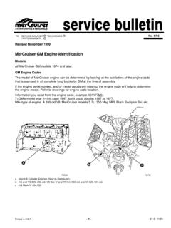
4 Terminalof the ignition coil will operate properly on the thunderbolt IV ignition 583- 2 -Troubleshooting thunderbolt IV (HEI) Ignition SystemThe thunderbolt IV ignition system is a relatively simple system. It consists of four components anda 12-volt source to operate it. The four components are: ignition coil, ignition amplifier, ignition sen-sor and sensor wheel (Figures 1 and 2).To troubleshoot the ignition system all that is needed is a voltmeter and spark gap - Rotorb - Sensor Wheelc - Ignition SensorFigure 1.
5 Distributor Components andIgnition Coild - Distributor Cape - Ignition Coila - Ignition AmplifierFigure 2. Ignition Amplifierabcdea- 3 - 83-24 583!WARNINGBe sure that engine compartment is well ventilated and that there are no gasoline vaporspresent during the following test to prevent a potential fire all Terminal Connectionsat Distributor, Ignition Amplifier &Ignition CoilBattery OK ?Dist. Clamping Screw Tight ?With Key in Run Position, Checkfor 12-Volt at Positive (+)Terminal on Ignition CoilCheck for 12-Volts at WHT/REDT erminal on DistributorRemove Hi-Tension Leadfrom Dist.
6 To a Spark Gap fromCoil Tower to WHT/GRN Lead fromDist. Terminal Ignition Key inRun Position. Strike theTerminal on the WHT/GRN LeadAgainst GroundReplace Ignition AmplifierSubstitute a New IgnitionCoil. Repeat Above TestCheck Engine& InstrumentWiring Harness,Battery Cables,Key SwitchReplaceIgnitionSensor inDistributorInstall NewIgnitionCoilNo Spark12 Volts12 VoltsNo Spark @ CoilReplaceIgnitionAmplifierDisconnect WHT/RED Lead FromDist. Term. ThenCheck for 12-Volton This LeadReplaceIgnitionSensor inDistributorNo Spark @ CoilSpark@CoilSpark@Coil0 Volts0 Volts12 Volts0 Volts83-24 583- 4 - thunderbolt IV Distributor Repair!
7 CAUTIONDO NOT USE any type of silicone sealer on the inside of the distributor. Most silicone sealersgive off an acidic vapor during the curing stage of the sealer. This acidic acid can cause cor-rosion on the ignition Remove 4 distributor cap attaching screws and remove Remove distributor rotor/sensor wheel assembly from distributor : If rotor and sensor wheel assembly cannot be removed by hand, remove as follows: Usetwo 3/8 ( ) wide flat blade screwdrivers approximately 8 ( ) to 10 ( ) long. Thescrewdrivers are positioned opposite each other with the blade tips on the underside of the rotorand sensor wheel assembly.
8 Make sure blade tips are toward distributor shaft until they come incontact with shaft. A downward push on both screwdriver handles at the same time will pry rotorand sensor wheel assembly off. The use of Torch Lamp (91-63209) will also aid in the removal ofthe rotor/sensor wheel With the rotor and sensor wheel assembly removed, inspect the locating key inside the rotor.(Use a penlight or suitable light to inspect.) (Figure 3)4. The locating key will appear as a clean edged, 1/8 ( ) wide, sloped ramp at the bottomof the splined If there are pieces of material shaved off of key or if it appears to have been damaged by beingforced down while misaligned with slot in distributor shaft, the rotor must be If rotor key is damaged, replace rotor by removing 3 phillips screws and separating sensor wheelfrom rotor.
9 Reinstall sensor wheel to new rotor making sure locating pin on rotor is installed inlocating hole in sensor wheel. Tighten 3 phillips screws securely. (Figure 3)7. Bend carbon brush tang upward slightly until a distance of 1/4 ( ) is obtained betweenrotor and tang. (Figure 4)a - Locating Keyb - Phillips Screwsc - Sensor Wheel Locating PinFigure 3. Locating Key Locationa - 1/4 ( )Figure 4. Rotor Assemblyabca- 5 - 83-24 58315520 Figure 5. Location of Cracks In Metal Jumper Leads on Ignition Sensor8. Use a good magnifying glass and light to inspect the two metal jumper leads for cracks(Figure 5).
10 If a crack is found in either metal jumper lead , install a new Place a small amount of Quicksilver 2-4-C Lubricant (92-86154A1) around distributor shaftwhere it enters the bronze bushing (Figure 6).NOTE: This will prevent any of the Loctite used in the next step from getting into bronze Put 2 drops of Loctite 271 or Loctite Type A into the rotor so it lands on the locating key. (Figure 3)11. Put 2 drops of Loctite in keyway on upper portion of distributor shaft. (Figure 6)12. Immediately install rotor assembly onto distributor shaft.