Transcription of TOOLING ALLOYS DATA SHEET CPM 10 V
1 P A G E 1/4 T O O LI N G A L L O Y S | C P M 1 0 V CHEMICAL COMPOSITION Carbon % Chromium % Vanadium % Molybdenum % Manganese % Silicon % CPM 10 V is a unique cold work tool steel produced by the special Crucible Particle Metallurgy process. It has been developed using a high-strength air-hardened base alloy with the addition of concentrated carbon and vanadium. As a result, the material CPM 10 V is characterized by a combination of outstanding wear resistance, toughness, hardness properties as well as excellent cutting edge stability.
2 Due to its extraordinarily high resistance to wear and outstanding toughness, CPM 10 V is particularly suitable for use together with hard materials or other highly resistant materials in cold working applications, in which tool breakage or chipping poses problems or where low-cost production is required. TYPICAL APPLICATIONS _ punching tools _ fine blanking tools _ punch dies _ knife blades for cutting, shearing and deburring _ paper and film cutters _ sinter press dies _ wear parts _ centre points _ machine parts and further more PHYSICAL PROPERTIES Modulus of elasticity E [kN/mm ] 221 Specific weight [kg/dm ] Coefficient of thermal expansion over temperature range of 21 - 593 C [mm/mm C]
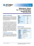
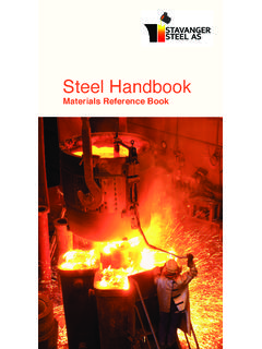
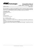
3 POWDER METALLURGICAL AND CONVENTIONAL MICROSTRUCTURE The uniform distribution of carbides in the powder- metallurgical structure compared to conventional tool steels with big carbides and carbide clusters. TOUGHNESS Charpy C-Notch impact test 01020304050D262M264 CPMREX M464 CPM10 V60 CPM10V64 JouleHRc Standard size of the Charpy-test-piece with a mm notch radius. WEAR RESISTANCE Charpy C-Notch impact test 0100200300400500600D260M264 CPMRex M464 CPM10 V60 CPM10 V64 104 MN/mm HRc Reciprocal of wear rate in wear test with non lubricated crossed cylinder in contact with a rotation tungsten carbide cylinder.
4 TOOLING ALLOYS DATA SHEET CPM 10 V ZAPP IS CERTIFIED TO ISO 9001 P A G E 2/4 TOOLI N G A L L O Y S | C P M 1 0 V HEAT TREATMENT ANNEALING SOFT ANNEALING The material is heated uniformly to a temperature of 870 - 900 C; maintain temperature for 2 hours and allow to cool to 540 C in the furnace at a cooling rate of 10 C per hour. This is followed by cooling in air. The typical hardness achieved by soft annealing is HB 248/269. STRESS RELIEVING Stress relieving follows rough machining by heating to a temperature of 600 700 C.
5 Once complete heat penetration has been reached, the material is allowed to cool in the furnace to approx. 500 C followed by cooling in air. HARDENING Hardening of CPM 10 V usually involves the use of 2 preheating stages (450 500 C/ 850 870 C). The material is then rapidly heated from the preheating temperature to the austenitizing temperature of 1070 C to 1180 C; 1070 C for achieving optimum toughness and 1180 C for achieving maximum wear resistance. To achieve a corresponding degree of dissolution of the alloy elements as well as an appropriate hardening and tempering level, a minimum heat penetration time of 30 min.
6 Is recommended for hardening at 1070 C and a minimum heat penetration time of 10 min. for hardening at 1180 C. These temperature equalisation times should be correspondingly adapted for large or very thick-walled material cross-sections. QUENCHING Air, hot bath or interrupted oil quenching can be used. We recommend hot bath quenching at approx. 550 C. Particular care must be taken in case of protective gas or vacuum heat treatment to ensure that an appropriate quenching rate is achieved in order to obtain the required hardness level at the recommended tempering temperature.
7 TEMPERING Temper immediately after the tools have been quenched to a temperature below 40 C. Two-stage tempering is obligatory while triple tempering is recommended particularly when hardening takes place at temperatures above 1150 C. It is important to ensure the tools are quenched to room temperature between the individual tempering processes. The standard tempering temperature is 540 C. With exception to the stress relieving procedure, temperatures below 540 C should be avoided in order to ensure effective tempering treatment.
8 TEMPERING DIAGRAM 505254565860626466540550565 Hardness HRc1070 C1180 CTempering temperature C HEAT TREATMENT INSTRUCTIONS 1st preheating 450 500 C 2nd preheating 850 900 C Hardening as specified in table Tempering 3 x each 2 hours at 540 C Quenching after hardening in hot bath at approx. 550 C or in vacuum at least at 5 bar overpressure. Required hardness HRc 1 Austenitizing temperature C Holding time at austenitizing temperature minutes* 59 1060 30 40 60 1080 30 40 61 1100 30 40 62 1120 20 30 63 1150 15 20 64 1180 10 15 * Previous preheating at 870 C.
9 The data referred to 13 mm round bar samples. The holding times at austenitizing temperature should be correspondingly adapted for large and very thin profile dimensions. The maximum permissible austenitizing temperature of 1180 C must not be exceeded. P A G E 3/4 TOOLI N G A L L O Y S | C P M 1 0 V MACHINING DATA TURNING Cutting parameter Turning with cemented carbide medium turning finish turning HSS Cutting speed (VC) m/min. 70-100 100-120 8-10 Feed (f) mm/U Cutting depth (ap) mm 2 4 2 3 Tools according ISO P 10 P 20* P 10* * Use wear resistant coated cemented carbide, Coromant 4015 or Seco TP 100.
10 MILLING FACE- AND EDGEMILLING Cutting parameter Milling with cemented carbide medium turning finish turning HSS Cutting speed (VC) m/min. 50-70 70-100 15 Feed (f) mm/U Cutting depth (ap) mm 2 4 1 2 1 2 Tools according ISO K 15* K 15* * Use wear resistant coated cemented carbide, Coromant 4015 or Seco TP 100. END MILLING Cutting parameter Solid carbide Milling cutter w. indexable tips Coated HSS Cutting speed (VC) m/min. 20 35 60-80 12* Feed (f) mm/U ** ** ** Tools according ISO K 20 P 25** * for TiCN-coated end mills made of HSS VC 25-30 m/min.