Transcription of Tools Required (not supplied) Sundries / Extras (not supplied)
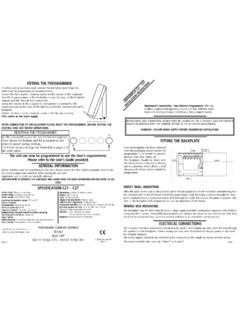
1 Installation and Safety InstructionsIP44 Recessed Downlight240V GU10 These instructions are for your safety. Please read through them thoroughly before use and retain for future Required (not supplied) Sundries / Extras (not supplied) 3mm Flat Blade Screwdriver6mm Cross Headed Screwdriver Power Drill66mm Hole Saw / Keyhole SawFilePencilInsulating TapeTerminal blockGU10 Lamp Max. 50 WSiting Instructions1) This product is suitable for indoor use ) Do not attach to surfaces which are damp, freshly painted or otherwise electrically conductive ( metallic surfaces).3) This fitting is not suitable for direct mounting on normally flammable surfaces, wood based materials.
2 It is suitable only for mounting on non-combustible surfaces plasterboard, masonry. Shown by the symbol on the ) The lamp must be positioned so that there is at least between the bulb and any illuminated surface (see below). Spotlights should be positioned well away from curtains and beds to ensure this distance is ) This product is specially designed for installation in a bathroom. It is IP44 rated and can be fitted in Zone 2 and Outside (dry) zones of a bathroom - see diagram below. 6) The bezel on this product provides the IP44 protection. The electrical parts of this product must be installed in a fully enclosed ceiling void with the bezel fitted to maintain the IP44 rating.
3 Do not use the product without the bezel You Start If you need any assistance please contact your local trade counter who will be able to help you. Decide on an appropriate location for your product (see siting instructions below). This product is not suitable for single-handed installation. An assistant will be Required during fitting. If you are in any doubt about installing this product, consult a qualified electrician. 413416776478571 Page 1 of 4 WindowrecessLESS .ACeiling PreparationHole Diameter: 66 MMMinimum Ceiling Cavity Depth: 140MM1) Ensure a minimum depth of ceiling void of 140mm is available.
4 See fig 1 on page ) When more than one down light is to be installed, the distance between units must be at least (30cm).3) Cut the 66mm diameter mounting holes in the ceiling taking care not to foul any pipes, mains cables or joists beneath the surface. 4) All measurements are based on a ceiling with a 12mm thickness. If your ceiling thickness is less than 12mm, deduct approximately 5mm from the ceiling diameter shown above. If the ceiling is thicker than 12mm, gradually increase the hole until a snug fit is achieved. It is always recommended to cut the hole slightly smaller than the size specified, and then file the hole until the recessed unit fits snugly.
5 5) Ensure free movement of air around the fitting by removing any roof void insulation from at least 100mm around the hole. Under no circumstances must these fittings be covered with insulating matting or similar fittings can be connected in star or parallel configurations. See diagram ) Draw the mains cable through the hole in the ceiling. (Use minimum mm2 core cable H03VV-F or equivalent).2) Open terminal block box by loosening screw. Loosen screws on cable clamp and fit supply wiring into cable clamp. (See Fig. 2) 3) Connect supply cable to the terminal box attached. Live supply to the Brown input cable and neutral supply to the Blue input cable.
6 (See Fig. 3) Terminate your Earth and Loop cables as necessary. Refit terminal block cover and tighten ) Fit terminal block bracket to downlight by sliding end of bracket into spring coil. (See Fig. 4)5) Check all connections are tight. Tighten cable clamp units are double insulated and must not be earthed. If there are any incoming earth cables, they must be joined together and well insulated with good quality insulation tape. This is to ensure earth continuity throughout your ) This product is suitable for use with dimmer switches when fitted with a halogen UnitSchematicStar WiringLNMainsInputRecessed UnitSchematicParallel WiringPage 2 of 47) If fitting in a bathroom this product must be supplied via a 30mA Residual Current Device (RCD) and installed by a competent person in accordance with the IEE wiring regulations BS7671 and local Building )
7 Expert advice should be sought before installing downlighters in any ceiling forming a fire barrier ceilings between flats *Refer to Electrical change sheet for old and new wiring cable colours IMPORTANT. Always switch off the electricity supply at the mains during installation and maintenance. We recommend that the fuse is withdrawn or circuit breaker switched off at the distribution board whilst work is in progress (turning off the lightswitch is not sufficient). All fittings must be installed by a competent person in accordance with current IEE Wiring Regulations (BS7671) and local Building Regulations.
8 If in doubt, consult a qualified replacement1) Switch off and allow bulb to cool before ) Pull-off front bezel to expose bulb. (Fig. 5) Unclip bulb from bezel. (Fig. 6)3) Remove old bulb by holding lampholder and turning bulb anticlockwise a quarter with bulb type 50W MAX. GU10 Halogen. Only use self-shielded halogen bulbsmarked with the symbol shown on the right. Alternatively, use equivalent energy saving LED or Compact Fluorescent GU10 ) Fit the new bulb into the lampholder, slide into bezel and refit bezel back onto product. Ensure bezel is securely fitted to maintain water-tight the ceiling surface is flat and smooth to ensure a good ) Always switch off or disconnect from the mains before installation.
9 2) Feed the supply cable through the mounting hole. Squeeze the spring clips upwards towards the ceiling and fit the arms into the ceiling hole (See below.) Take care when releasing your grip as the springs will snap back and push against the back of the ) Ensure the cable is kept away from the lamp body to ensure it is not subjected to excess heat from the ) Push the unit upward until firmly in position, ensuring that the cable is not trapped. 5) Remove front bezel by pulling ) Obtain a suitable bulb - 50W Max GU10 Halogen or equivalent energy saving LED or compact Fluorescent GU10 bulb. See Bulb replacement section below on how to ) Replace the circuit fuse and switch on the mains to 3 of 4 Powersmith Ltd, BA22 8RT150mm300mm140mmNNLLFig.
10 3 Fig. 2 Fig. 4 Fig. 5 Fig. 6 Fig. 1 Care & Use Always switch off or disconnect from the mains when cleaning the product. Wipe clean with a soft dry cloth. Never use scourers, abrasives or chemical cleaners. Do not allow moisture to come into contact with electric parts. If the glass shield becomes cracked or damaged it must be replaced. Do not use the product without front bezel CrackedShadeAs of 1 January 2005, changes to the Building Regulations affected domestic electrical installations in England and don t need to be a qualified electrician to make changes to your home s electrical system, but the work must be done in accordance with the standards in the do not need to notify your LocalAuthority if you do minor electrical work such as.


