Transcription of Topic 11 - Seismic Design of Reinforced Concrete Structures
1 FEMA 451B Topic 11 NotesReinforced Concrete Structures 11 - 1 Instructional Material ComplementingFEMA 451, Design ExamplesDesign for Concrete Structures 11 - 1 Seismic Design OF Reinforced Concrete STRUCTUREST opic 11 is the Seismic Design of Reinforced Concrete Structures , primarily buildings. During this lesson you will learn the basics of Seismic Design of Reinforced Concrete buildings. Buildings designed using these principles will fare better in a Seismic event than the building shown in this that some of the examples in this Topic draw heavily on the examples in the FEMA 451, NEHRP Recommended Provisions: Design Examples. Please see Chapter 6 of that CD for additional details regarding these 451B Topic 11 NotesReinforced Concrete Structures 11 - 2 Instructional Material ComplementingFEMA 451, Design ExamplesDesign for Concrete Structures 11 - 2 NEHRP Recommended ProvisionsConcrete Design Requirements Context in the NEHRP Recommended Provisions Concrete behavior Reference standards Requirements by Seismic Design Category Moment resisting frames Shear walls Other topics SummaryThis slide presents the outline of this presentationFEMA 451B Topic 11 NotesReinforced Concrete Structures 11 - 3 Instructional Material ComplementingFEMA 451, Design ExamplesDesign for Concrete Structures 11 - 3 Context in NEHRP Recommended ProvisionsDesign basis: Strength limit stateUsing NEHRP Recommended Provisions:Structural Design criteria:Chap.
2 4 Structural analysis procedures:Chap. 5 Components and attachments:Chap. 6 Design of Concrete Structures :Chap. 9 andACI 318 The 2003 NEHRP Recommended Provisions(FEMA 450) uses strength limit state for Design of Concrete (and all other materials). Since ACI 318 provides ultimate strength procedures, the Provisionsdesign will be very familiar to most engineers. Required strength (demand) is determined from ProvisionsChapters 4 and 5 and provided strength (capacity) is calculated using Chapter 9. The chapters of Provisionsthat affect Concrete Design are as follows: Chapter 4 for loadcombinations and Rand Cdfactors, Chapter 5 for Seismic load determination and distribution, Chapter 6 for specific component and attachment requirements, and Chapter 9 for the Design of Concrete elements and connections. Chapter 9 also provides detailing provisions that are used to ensure stable inelastic 451B Topic 11 NotesReinforced Concrete Structures 11 - 4 Instructional Material ComplementingFEMA 451, Design ExamplesDesign for Concrete Structures 11 - 4 Seismic -Force-Resisting SystemsReinforced ConcreteUnbraced frames (withrigid moment resisting joints):Three typesOrdinaryIntermediateSpecialR/C shear walls:OrdinarySpecialPrecast shear walls:SpecialIntermediateOrdinaryTwo possible Seismic resisting systems using Reinforced Concrete are moment frames and shear walls.
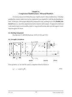
3 ProvisionsChapter 4 presents Design coefficients and system limitations for various Seismic Design Categories. Precast walls can be used, however they will not be addressed in detail in this lecture. To understand some of the detailing requirements and how they relate to the ductility of these structural systems, we will first review basic Reinforced Concrete 451B Topic 11 NotesReinforced Concrete Structures 11 - 5 Instructional Material ComplementingFEMA 451, Design ExamplesDesign for Concrete Structures 11 - 5 NEHRP Recommended ProvisionsConcrete Design Context in the Provisions Concrete behaviorThis section will discuss mechanical properties of reinforcing steel and Concrete and how the two materials work together in Reinforced Concrete 451B Topic 11 NotesReinforced Concrete Structures 11 - 6 Instructional Material ComplementingFEMA 451, Design ExamplesDesign for Concrete Structures 11 - 6 Unconfined Concrete Stress-Strain , , psi4500 psi8800 psi13,500 psi17,500 psiThis slide presents stress-strain diagrams for unreinforced, unconfined Concrete in compression.
4 Behavior is relatively linear up to about one-half of the maximum compressive stress. Concrete exhibits no precise yield point. Strain at maximum strength is close to regardless of maximum stress. Lower strength Concrete can have strains at crushing that exceed , however a typical Design value is at crushing. Stronger concretes are more 451B Topic 11 NotesReinforced Concrete Structures 11 - 7 Instructional Material ComplementingFEMA 451, Design ExamplesDesign for Concrete Structures 11 - 7 Idealized Stress-Strain Behaviorof Unconfined , psi2''6' 10460 ,ccccoocottcfffEExfpsi = ==+This slide shows one commonly used, relatively simple, idealized model of the stress-strain behavior of unconfined Concrete (Hognestad). This type of mathematical model can be used in a strain compatibility approach to predict behavior of Reinforced Concrete 451B Topic 11 NotesReinforced Concrete Structures 11 - 8 Instructional Material ComplementingFEMA 451, Design ExamplesDesign for Concrete Structures 11 - 8 Confinement by Spirals or HoopsAspdsfyhAspfyhAspConfinementfrom spiral orcircular hoopForces actingon 1/2 spiral orcircular hoopConfinementfrom squarehoopConfining reinforcing can improve Concrete behavior in two ways.
5 First it can enhance strength by restraining lateral strains. Second it can increase the usable Concrete compressive strain well beyond the typical value of slide shows confinement in practical structural sections. Confinement is typically provided by spirals, circular hoops, or square hoops. The hatched areas in the figures may spall. Confining steel is in tension (hoop stress effect) because, due to Poisson s effect, as the Concrete is compressed in one direction, it expands in the orthogonal directions. This is shown in the center illustration. Note that hoops are not as efficient as spirals in confining Concrete because the sides of the hoop can flex outward as the confined Concrete expands 451B Topic 11 NotesReinforced Concrete Structures 11 - 9 Instructional Material ComplementingFEMA 451, Design ExamplesDesign for Concrete Structures 11 - 9 ConfinementRectangular hoopswith cross tiesConfinement bytransverse barsConfinement bylongitudinal barsThis slide shows confinement for a square column, which can be provided by transverse and longitudinal bars.
6 The hatched areas may 451B Topic 11 NotesReinforced Concrete Structures 11 - 10 Instructional Material ComplementingFEMA 451, Design ExamplesDesign for Concrete Structures 11 - 10 Opened 90 hook on hoopsThis slide shows 90 degree hooks on square hoops which have opened. As stated earlier, the confining steel is in tension. After spalling, the hooks can open up. The solution is to use 135 degree hooks. The arrow points to an open 451B Topic 11 NotesReinforced Concrete Structures 11 - 11 Instructional Material ComplementingFEMA 451, Design ExamplesDesign for Concrete Structures 11 - 11 Confined Concrete Stress-Strain strain on in. gauge lengthStress, psino of in. of 6 in. x 12 in. cylindersThis slide shows the benefits of confinement on Concrete behavior. Presented are stress-strain diagrams for confined Concrete in compression. The specimens were 6 in. by 12 in. cylinders. Confinement was provided by spiral reinforcement.
7 Reducing spiral pitch (or hoop spacing) increases maximum Concrete stress and strain capacity (ductility).FEMA 451B Topic 11 NotesReinforced Concrete Structures 11 - 12 Instructional Material ComplementingFEMA 451, Design ExamplesDesign for Concrete Structures 11 - 12 Idealized Stress-Strain Behavior of Confined ConcreteKent and Park , , psiNo Hoops4 Area 12 x 16 This slide shows the idealized stress-strain behavior of confined Concrete proposed by Kent and Park. Note that the model reflects the additional strain, but not the additional strength, provided by the confinement. Another model that reflects both strength and strain gain is Scott, Park, and Priestley. This type of model can be used with the strain compatability method to predict the behavior of confined Reinforced 451B Topic 11 NotesReinforced Concrete Structures 11 - 13 Instructional Material ComplementingFEMA 451, Design ExamplesDesign for Concrete Structures 11 - 13 Reinforcing Steel Stress-Strain BehaviorStress, ksiMicrostrain10002000300040005000600070 00800020406080100 Grade 40 Grade 60 Grade 75E = 29,000 ksistrain hardening~ 1-3%rupture ~18-20%rupture~10-12%This slide shows typical stress-strain behavior of common grades of reinforcing steel.
8 The most commonly used is Grade 60 which shows a distinct yield plateau and strain hardening at between and 1% elongation. For common analysis of Reinforced Concrete behavior, strain hardening is ignored. For Seismic Design , it is important that the actual yield strain of the steel is not significantly higher than the value used in 451B Topic 11 NotesReinforced Concrete Structures 11 - 14 Instructional Material ComplementingFEMA 451, Design ExamplesDesign for Concrete Structures 11 - 14 LoadMid-Point Displacement, uncrackedcracked-elasticcracked-inelasti csteelyieldsfailureReinforced Concrete BehaviorThis slide shows stages of behavior of a Reinforced Concrete beam. At low loads the section is uncracked and an analysis using uncracked-transformed section properties can be used to predict behavior. After the Concrete cracks, the Concrete on the tension side of the beam is neglected, and a cracked-transformed section analysis can be used to predict behavior.
9 However, this method is only valid as long as both the steel and the Concrete stress-strain behaviors are linear. Concrete can be assumed to have a linear stress-strain behavior up to approximately 50% of maximum Concrete stress (f c).After the Concrete stress exceeds about 50%f c,a strain compatibility approach can be used, using a realistic Concrete stress-strain model such as the Hognestadmodel presented in Slide 7. After the steel yields, there is typically an extended plateau in which the displacement increases significantly with very little increase in applied load. A commonly used indicator of member ductility is the ratio of the displacement at ultimate to the displacement at first yield. This is known at the displacement ductility, and for Seismic Design in particular, bigger is 451B Topic 11 NotesReinforced Concrete Structures 11 - 15 Instructional Material ComplementingFEMA 451, Design ExamplesDesign for Concrete Structures 11 - 15 Behavior Up to First Yield of SteelbAsd s cStrain sStressE < fsyfccTo characterize section behavior, moment-curvature (M- ) diagrams are often employed.
10 This slide shows the type of strain compatibility approach that would be used to locate points on the curve up until first yield of the steel. To locate a point, first a Concrete strain is selected. Then an iterative method is used in which the depth to the neutral axis is assumed and modified until internal equilibrium is achieved. The tension force is equal to the strain (based on the strain diagram with the selected Concrete strain and neutral axis depth) times the area and the modulus of elasticity of the steel. The compression force is determinedby integrating under the stress-position curve from the neutral axis to the extreme compression fiber, and multiplying by the width of the beam. The value of c is adjusted until C = T. Then the curvature is calculated as the Concrete strain divided by the neutral axis depth, and the moment is the force (T or C) times the distance between the forces. This can be repeated for several selected Concrete strains to determine points on the M- 451B Topic 11 NotesReinforced Concrete Structures 11 - 16 Instructional Material ComplementingFEMA 451, Design ExamplesDesign for Concrete Structures 11 - 16 Behavior at Concrete CrushingbAsd s c,maxStrainStressfyf'cc y>ForcesA fysCjdMn= AsfyjdAfter yield but before the onset of strain hardening, the same method as presented on the previous slide can be used; however, the force in the steel will be Asfy.