Transcription of Torque Diagram and Torsional Stress of Circular Section
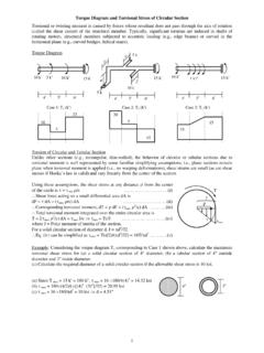
1 1 Torque Diagram and Torsional Stress of Circular Section Torsional or twisting moment is caused by forces whose resultant does not pass through the axis of rotation (called the shear center) of the structural member. Typically, significant torsions are induced in shafts of rotating motors, structural members subjected to eccentric loading ( , edge beams) or curved in the horizontal plane ( , curved bridges, helical stairs). Torque Diagram Case 1: T1 (k) Case 2: T2 (k) Case 3: T3 (k) torsion of Circular and Tubular Section Unlike other sections ( , rectangular, thin -walled), the behavior of Circular or tubular sections due to Torsional moment is well represented by some familiar simplifying assumptions; , plane sections remain plane when Torsional moment is applied ( , no warping deformations), shear strains are small (as are shear stesses if Hooke s law is valid) and vary linearly from the center of the Section .
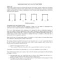
2 Example: Considering the Torque Diagram T1 corresponding to Case 1 shown above, calculate the maximum Torsional shear Stress for (a) a solid Circular Section of 4 diameter, (b) a tubular Section of 4 outside diameter and 3 inside diameter. (c) Calculate the required diameter of a solid Circular Section if the allowable shear Stress is 10 ksi. (a) Since T max = 15 k = 180 k, max = 16 180/(4)3 = ksi (b) max = 180(4/2)/({(4)4(3)4}/32) = ksi (c) max = 16 180/d3 = 10 ksi d = 3 T max c 5 k 10 k 15 k 10 k 1 k/ 15 k 5 k 10 k 5 k 10 k 15 k 4 5 6 4 5 6 3 2 4 5 6 10 5 15 20 5 15 10 15 Using these assumptions, the shear Stress at any distance from the center of the circle is = max /c ..(i) Shear force acting on a small differential area dA is dF = dA = (max /c) dA ..(ii) Corresponding Torsional moment, dT = dF = (max 2/c) dA ..(iii) Total Torsional moment integrated over the entire Circular area is T = (max 2/c) dA = max J/c max = Tc/J.
3 (iv) where J = Polar moment of inertia of the Section . For a solid Circular Section of diameter d, J = d4/32 Eq. (iv) can be simplified as max = T(d/2)/(d4/32) = 16T/d3 ..(v) 4 4 3 2 Torsional Rotation of Circular Section Calculation of Torsional rotation is necessary to 1. design structures not only to be strong enough (to withstand Torsional Stress ), but also stiff enough ( , they should not deform too much due to Torsional moments), 2. design machineries for Torsional vibrations, 3. analyze statically indeterminate structures. Torsional Rotation of Circular and Tubular Section The assumptions used to derive the equation for Torsional shear Stress of Circular sections are valid here also; , plane sections remain plane due to Torsional moment, shear strains (as well as stresses if Hooke s law is valid) are small and vary linearly from the center of the Section . where is integration between sections A and B. If T, J and G are uniform between A and B, then B A = (TL/JG).
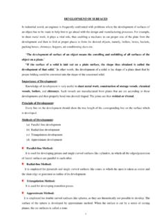
4 (v) Example: Considering the Torque Diagram shown below, calculate the Torsional rotations for (a) a tubular Section of 4 outside diameter and 3 inside diameter. (b) Calculate the required diameter of a solid Circular Section if the allowable Torsional rotation is 1 [Given: G = 12000 ksi]. (a) The polar moment of inertia of the tubular Section is J = {(4)4(3)4}/32 = in4 D C = (TL/JG)CD = (15 12) (6 12)/( ) = rad C = rad = C B = (TL/JG)BC = (5 12) (5 12)/( ) = rad B = rad = B A = (TL/JG)AB = (10 12) (4 12)/( ) = rad A = rad = (b) Using D = 0, the maximum Torsional rotation at point A is A = [(TL/JG)CD + (TL/JG)BC + (TL/JG)AB] /180 = [(15 12) (6 12) + (5 12) (5 12) + (10 12) (4 12)]/(J12000) = J = d4/32 = in4 d = T (k) O N M1 max d For a cylindrical segment of differential length dx, the length of the arc MN is given by ds = max dx ..(i) It can also be expressed in terms of the differential angular rotation d, , ds = c d.
5 (ii) where c = radius of the Circular area. Combining Eq. (i) and (ii) c d = max dx = (max/G) dx Using max = Tc/J c d = (Tc/JG) dx d = (T/JG) dx ..(iii) where J = Polar moment of inertia of the Section . Integrating between sections A and B B A = (T/JG) dx ..(iv) 4 dx 4 5 6 D C A B 10 k 5 k 10 k 15 k d 3 10 5 15 3 torsion of closed thin -Walled Sections thin -walled sections have wall thickness much smaller than its other dimensions. closed thin -walled sections are widely used in structures subjected to Torsional moments because compared to other sections, they can resist Torsional Stress and deformations more efficiently. Torsional Stress and Rotation of thin -Walled Section thin -walled sections can be analyzed for torsion using somewhat similar assumptions as for Circular sections; , plane sections remain plane, shear strains are small. However, since the thickness of the Section is very small, the shear stresses remain almost constant across the thickness instead of varying linearly from the center of rotation.
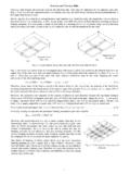
6 Also, the external energy required by a Torque T to cause a twisting rotation d is = T d/2 ..(iv) while the corresponding internal energy is = 2/2G dV = (T2/8 2t2G) (dx t ds) = (T2 dx /8 2G)(ds/t) ..(v) Eq. (iv) and (v) d/dx = (T/4 2 G)(ds/t); , Jeq = 4 2/(ds/t) ..(vi) Example: Considering the Torque Diagram shown below, calculate the maximum shear Stress and Torsional rotation for a 4 4 hollow square Section with wall thickness [Given: G = 12000 ksi]. The enclosed area = = in2 max = T/(2 t) = (15 12)/(2 ) = ksi Also Jeq = 4 2/ds/t = 4( )2/(4 ) = in4 D C = (TL/JG)CD = (15 12) (6 12)/( ) = rad C = rad = C B = (TL/JG)BC = (5 12) (5 12)/( ) = rad B = rad = B A = (TL/JG)AB = (10 12) (4 12)/( ) = rad A = rad = T (k) But the shear Stress does not remain constant throughout the perimeter of the Section .
7 Instead the shear flow q, which is the shear force per unit length (given by shear Stress times the wall thickness t ; , q = t) is constant. Shear force on a small element of length ds is dF = q ds ..(i) and the corresponding Torque dT = r dF = q r ds ..(ii) Since the area of the small triangular area subtended at the center of rotation is = rds, integrating rds over the perimeter of the area will give twice the entire area enclosed by the Section [ , 2 ]. Total Torque T = dT = q r ds = q 2 = q/t = T/(2 t) ..(iii) 4 10 5 15 4 5 6 D C A B 10 k 5 k 10 k 15 k 4 dx T ds dF r A A A A A A A thick wall A A A 4 torsion of Rectangular Sections Since a majority of civil engineering structures consist of rectangular or assembly of rectangular sections, the study of Torsional behavior of such sections is important. However, when subjected to Torsional moment, rectangular sections do not behave like Circular or thin -walled sections, due to the warping deformations accompanying their response.
8 Torsional Stress and Rotation of Rectangular Section The Torsional response of these sections cannot be derived using the simple methods of Strength of Materials, and requires concepts of Theory of Elasticity instead, which is beyond the scope of this course. Therefore, only the final expressions for Torsional Stress and rotation are shown here. b/t Example: Considering the Torque Diagram shown below, calculate the maximum shear Stress and Torsional rotation for a (a) 4 4 solid Section (b) 4 4 open Section [Given: G = 12000 ksi]. (a) For the 4 4 solid Section , = , = max = T/(bt2) = (15 12)/( 4 42) = ksi Also Jeq = bt3 = 4 43 = in4 D A = {(1512)(612) + (512)(512) + (1012)(412)}/( ) = rad A = rad = (b) The 4 4 open Section is torsionally equivalent to a rectangular Section of size 16 b/t = 32 Both and can be assumed to be max = T/(bt2) = (15 12)/( 16 ) = 135 ksi Jeq = bt3 = 16 = in4 D A = {(1512) (612) + (512) (512) + (1012) (412)}/( 12000) = rad A = rad = 160 Obviously, common structural materials cannot survive such a large shear Stress and angular rotation.
9 T (k) For a (bt) rectangular Section (with b t) subjected to Torsional moment T, the maximum shear Stress max = T/(bt2) ..(i) and the equivalent polar moment of inertia for Torsional rotation is Jeq = bt3 ..(ii) Torsional rotation for a uniform Section of length L is = TL/(bt3)G ..(iii) The constants and in Eqs. (i) and (ii) are non-dimensional parameters and depend on the ratio b/t, as shown in the following table. 4 10 5 15 4 5 6 D C A B 10 k 5 k 10 k 15 k 4 max t b 4 5 Distributed torsion and Torsional Rotation Since the loads on civil engineering (or other) structures are often distributed over a length or over an area, Torsional moments on such structures seldom work as concentrated at one Section . The Torque Diagram and calculation of Torsional rotation in such cases require special attention. Distributed torsion Case 1: T1 (k) Case 2: T2 (k) Example: Considering the Torque diagrams shown above, calculate the maximum Torsional rotation for a solid Circular Section of 4-diameter [Given: G = 12000 ksi].
10 The polar moment of inertia of the Circular Section is J = (4)4/32 = in4 Using D = 0, the maximum Torsional rotation at point A is (a) A = [(TL/JG)CD + BC(T/JG) dx + (TL/JG)AB] = [(15 12) (6 12) + {(10 +15)/2 12} (5 12) +(10 12) (4 12)]/( ) = rad = (b) A = [(TL/JG)CD + BC(T/JG) dx + (TL/JG)AB] = [(15 12) (6 12) + {(10 +5/3) 12} (5 12) +(10 12) (4 12)]/( ) = rad = D C B A D C B A 10 15 10 15 10 k 2 k/ 15 k 10 k 1 k/ 15 k 4 5 6 4 5 6 6 Composite and Variable Cross-sections Composite Sections Instead of the simple sections ( , Circular , thin -walled and rectangular), structures subjected to torsion may be sections of arbitrary shape or composite sections made up of two or more simple sections. While arbitrary shaped sections can only be dealt numerically, composites of two or more simple sections can be solved more conveniently. The basic assumption for solving this type of problems is that when subjected to torsion , the Section rotates as a rigid body; , = TL/JG is valid for each part of the Section so that = T1L/J1G1 = T2L/J2G2, etc.