Transcription of Torque Sensor Technical Information - PCB Piezotronics
1 Piezotronics , Inc. Toll-Free in USA 888-684-0004716-684-0001 SensorTechnical Informationn Introduction to Torque sensorsn Glossary of termsHighlightsFigure 1. Wheatstone BridgeFigure 2. Series 2300 Reaction Torque Sensor Wiring CodeFigure 3. Series 4100 Rotary Transformer Torque Sensor Wiring CodeFigure 4. Series 4200 Rotary Transformer Torque Sensor Wiring CodeFigure 5. Right-handed OrthogonalCoordinate SystemPrinciple of OperationAll Torque sensors manufactured by PCB are strain gage based measuring instrumentswhose output voltage is proportional to applied Torque . The output voltage produced bya resistance change in strain gages that are bonded to the Torque Sensor structure. Themagnitude of the resistance change is proportional to the deformation of the torquesensor and therefore the applied four-arm Wheatstone Bridge configuration shown in Figure 1depicts the strain gagegeometry used in the Torque Sensor structures.
2 This configuration allows for temperaturecompensation and cancellation of signals caused by forces not directly applied about theaxis of the applied Torque . A regulated 5 to 20 volt excitation is required and is applied between points A and D ofthe Wheatstone bridge. When Torque is applied to the transducer structure theWheatstone bridge becomes unbalanced, thereby causing an output voltage betweenpoints B and C. This voltage is proportional to the applied 2300 reaction Torque sensors have the wiring code illustrated in Figure 2. Series 4100 rotary transformer Torque sensors have the wiring code illustrated in Figure 4200 rotary transformer Torque sensors have the wiring code illustrated in Figure DefinitionPCB Torque sensors comply with the Axis and Sense Definitions of NAS-938 (NationalAerospace Standard-Machine Axis and Motion) nomenclature and recommendations ofthe Western Regional Strain Gage are defined in terms of a right-handed orthogonal coordinate system, as shown inFigure principal axis of a transducer is normally the z-axis.
3 The z-axis will also be the axisof radial symmetry or axis of rotation. In the event there is no clearly defined axis, thefollowing preference system will be used: z, x, y. Piezotronics , Inc. Toll-Free in USA 888-684-0004716-684-0001 to Torque SensorsFigure 6. Axis and Sense Nomenclature for Torque SensorsFigure 7. Common Torque Sensor Configurations Keyed ShaftSpline DriveThe principal axis of a transducer is normally the z-axis. The z-axis will also be the axisof radial symmetry or axis of rotation. In the event there is no clearly defined axis, thefollowing preference system will be used: z, x, y. Figure 6shows the axis and sense nomenclature for our Torque sensors. A (+) signindicates Torque in a direction which produces a (+) signal voltage and generally definesa clockwise Sensor Structure DesignTorque Sensor structures are symmetrical and are typically manufactured from steel (SAE4140 or 4340) that has been heat-treated Rc 36 to 38.
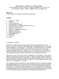
4 Common configurations are solidcircular shaft, hollow circular shaft, cruciform, hollow cruciform, solid square, and hollowtube with flats. The solid square offers advantages over the solid circular design, especially in capacitiesgreater than or equal to 500 in-lb (55 N-m). The solid square offers high bending strengthand ease of application of strain gages. Torque sensors with capacities less than 500 in-lb (55 N-m) are usually of the hollow cruciform type. The hollow cruciform structureproduces high stress at low levels of Torque , yet has good bending strength. Commonconfigurations are shown in Figure variety of end configurations are available, including: keyed shaft, flange, and spline.(See below).Reaction Torque SensorsTypical reaction Torque Sensor applications include:nBearing frictionnStarter testingnStepping switch torquenAutomotive brake testingnAxle torsion testReaction Torque is the turning force or moment, imposed upon the stationary portion ofa device by the rotating portion, as power is delivered or absorbed.
5 The power may betransmitted from rotating member to stationary member by various means, such as themagnetic field of a motor or generator, brake shoes or pads on drums or rotors, or thelubricant between a bearing and a shaft. Thus, reaction Torque sensors become usefultools for measuring properties such as motor power, braking effectiveness, lubrication,and Torque sensors are suitable for a wide range of Torque measurementapplications, including motor and pump testing. Due to the fact that these sensors do notutilize bearings, slip-rings, or any other rotating elements, their installation and use canbe very cost effective. Reaction Torque sensors are particularly useful in applicationswhere the introduction of a rotating inertia due to a rotating mass between the drivermotor and driven load is undesirable. An example of this can be found in small motortesting, where introduction of a rotating mass between the motor and load device willresult in an error during acceleration.
6 For these applications, the reaction Torque sensorcan be used between the driver motor, or driven load, and ground. An added benefit isthat such an installation is not limited in RPM by the Torque Sensor . PCB manufacturesreaction Torque sensors with capacities ranging from a few inch ounces to 500k in-lb( N-m), in configurations including keyed shaft and flange. Piezotronics , Inc. Toll-Free in USA 888-684-0004716-684-0001 to Torque SensorsRotary Torque SensorsTypical rotary Torque Sensor applications include:nChassis dynamometernClutch testingnEngine dynamometernBlower or fan testingnEfficiency testingnSmall motor / pump testingRotating Torque sensors are similar in design and in application to reaction torquesensors, with the exception that the Torque Sensor is installed in-line with the deviceunder test. Consequently, the Torque Sensor shaft rotates with the device under test.
7 InPCB Series 4100 and 4200 models, the rotating Torque Sensor shaft is supported in astationary housing by two bearings. Signal transfer between the rotating Torque sensorshaft and the stationary housing is accomplished by means of rotary TransformersRotary Transformers provide a non-contact means of transferring signals to and from therotating Torque Sensor structure. Rotary transformers are similar to conventionaltransformers, except that either the primary and secondary winding is rotating. Forrotating Torque sensors, two rotary transformers are used. One serves to transmit theexcitation voltage to the strain gage bridge, while the second transfers the signal outputto the non-rotating part of the transducer. Thus no direct contact is required between thestationary and rotating elements of the transducer (see Figure 8).Rotary transformers are made up of a pair of concentrically wound coils, with one coilrotating within or beside the stationary coil.
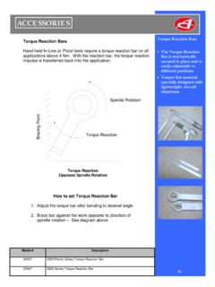
8 The magnetic flux lines are produced byapplying a time varying voltage (carrier excitation) to one of the coils (see Figure 9). Figure 10depicts a typical rotary transformer Torque Sensor :Transmission of energy through any transformer requires that the current be suitable signal conditioner with carrier excitation in the range of 3 to 5000 Hz isrequired to achieve Installation of Keyed Shaft Torque SensorsProper installation must be observed when assembling a Torque Sensor into a selection of components must be made so that problems are not created whichcould lead to part failure or danger to misalignmentProvision must be made to eliminate the effects of bending and end loading on thetorque sensors shaft due to parallel offset of shafts, angular misalignment, and shaft endfloat. The proper use of couplings can reduce these problems to a negligible shafts must first be aligned mechanically, as accurately as possible, to lessen thework the couplings must do.
9 Alignment within inch per inch of shaft diameter isnormally satisfactory, however, for some critical applications such as high speed, thislevel of alignment is not acceptable, and a tighter tolerance must be achieved. Pleasecontact our factory, or your coupling vendor, for Information regarding your Sensor with foot-mounted housing installationA foot-mounted Torque Sensor has a plate on its housing, which can be securely attachedto a machine base or bedplate. This installation reduces the mass in suspension on thecouplings and can increase the shaft s critical speed, if the Torque Sensor is within itsspeed rating. Normally, if both the driving and load sources are fully bearing-supportedin foot-mounted housings, and the Torque Sensor housing is foot-mounted, double-flexcouplings should be used on each shaft end. Double-flex couplings provide for twodegrees of freedom, meaning they can simultaneously allow for angular and parallelmisalignment, and reduce the effects of bending on the Torque Sensor shaft.
10 Half of eachcoupling weight is supported on the Torque Sensor s shaft, and the other half is carriedby the driving and load 8. Figure 9. Figure 10. Rotary Transformer Torque Sensor Diagram Piezotronics , Inc. Toll-Free in USA 888-684-0004716-684-0001 to Torque SensorsTorque Sensor with floating shaft installationA floating shaft Torque Sensor does not have a foot-mount plate on the housing, nor isthe housing affixed to a bedplate in any other fashion. It depends on being carried by thedriver and load shafts for its support. The housing, which is meant to remain stationaryand not rotate with the shaft, must be restrained from rotating with a conductive flexiblestrap. Tapped threaded holes are provided on the side of the housing for this other end of the strap is bolted to a bedplate or other stationary-grounded member,which will electrically ground the Torque Sensor housing to the electrical system ground.