Transcription of Total Organic Carbon The Pitfalls of Process TOC
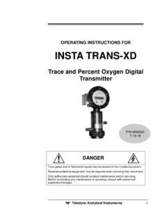
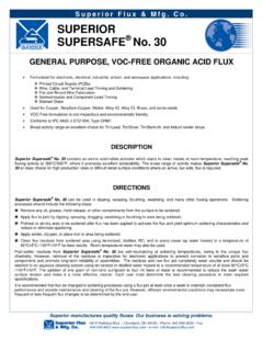
1 Total Organic CarbonTeledyne Analytical InstrumentsThe Pitfalls of Process TOCAnd how to avoid themINTRODUCTIONS ince the introduction of Total Organic Carbon (TOC) Analyzers by Dow, Union Carbide and Automated Environmental Systems in the1960s(1,5), they have proven to be an invaluable tool in the environmental and Process monitoring fields. While technologies have advanced since then, certain performance characteristics required for true Process control have been notably purpose of this paper is to discuss those limitations as evidenced by field experience, maintenance requirements and other practical considerations. Failure mode and effect analyses are summarized for critical components, as well as suggested corrective design, operation, and maintenance approaches, with a view toward minimizing cost of TOC ANALYSISG enerally, all TOC Analyzers employ the same basic technique as depicted in figure 1.
2 A liquid sample is initially introduced to an Inorganic Carbon (IC) removal stage, where acid is added to the sample, dropping its pH to approximately At this point, the IC is converted to Carbon dioxide (CO2) gas, which is stripped out of the liquid by a sparge carrier gas. The remaining inorganic Carbon -free sample is then delivered to the Oxidation Chamber. The Oxidation Chamber is normally either a chemical reagent (Persulfate) with an Ultraviolet (UV) Lamp Reactor(4) or a High Temperature Combustion Reactor(3) for catalytic or non-catalytic oxidation. The Reactors oxidize the remaining Organic Carbon to CO2 gas, which is directed to and measured by the CO2 gas detector. The CO2 gas detector is a Non- Dispersive-Infrared Analyzer (NDIR), to meet EPA and ASTM Standards(3,4) and provide interference-free detection of CO2 gas.
3 The CO2 generated from the oxidation Process is directly related to the TOC in the the principle objective of this paper is to provide a guide to avoid common TOC operational problems, a brief description of the chemical analysis should be given since there has been some unnecessarily complicated treatment of sub-categories of Organic Carbon . Quite simply, do you need to measure volatile and purgeable Organic Carbon , as well as dissolved and suspended-solid Organic Carbon , for a true TOC analysis or not? If only the dissolved and suspended solid TOC are of interest, categorized as NPOC (Non-Purgeable- Organic - Carbon ), then a TOCDIRECT measurement will suffice. Figure 1 illustrates the TOCDIRECT method. It indicates the physical effect of flowing a sparge carrier gas through the INORGANIC Carbon SPARGER to strip out the dissolved CO2, created by the acidification Process to remove the inorganic Carbon from the sample, as previously described.
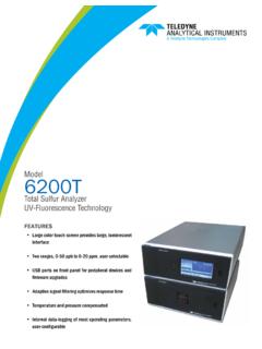
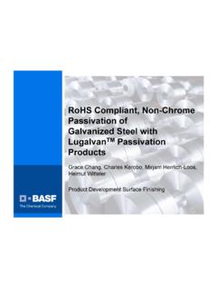
4 Note that POC (Purgeable Organic Carbon ) and VOC (Volatile Organic Carbon ) are also stripped out and lost to analysis. If the measurement of all the Organic Carbon is required, then a TOCTRUE analysis must be made. Figure 2 shows both the TOCDIRECT and TOCTRUE methodologies. In the TOC true method, both the CO2 gas from the SPARGER and the CO2 gas generated from oxidizing the complete sample are measured. A computed differential measurement yields all of the Organic Carbon content for a complete, or TRUE , TOC from pure Process control requirements, Regulatory Agencies may require analysis of all the Organic Carbon species for the discharged waste Pitfalls of Process TOCF igure 1 Figure 2 Total Organic CarbonTeledyne Analytical InstrumentsOXIDATION METHOD(Do I select UV/PERSULFATE or HIGH TEMPERATURE COMBUSTION?)
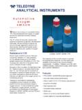
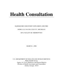
5 After determination of the TOCDIRECT and TOCTRUE question, the important choice of oxidation method must be made. While the details of this subject exceed the scope of this paper, the existing basic rule of thumb may be stated as:a) For low level TOC analysis, undiluted ranges up to 2000 ppm (parts-per-million) Carbon , no salts (or diluted to a very low level), and significantly less maintenance, UV/PERSULFATE oxidation should be ) For difficult-to-oxidize or salt-containing samples, high levels of Carbon , or method preference, HIGH TEMPERATURE COMBUSTION should be selected for those MODES AND EFFECTSIn order to clarify potential failure points and for purposes of illustration, a conventional Process UV/Persulfate TOC is shown in figure 3(12).
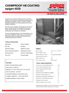
6 Figure 4 depicts a conventional High Temperature Combustion TC ( Total Carbon ) / TOC Analyzer.(10)Table 1 defines summary failure modes and effects, along with suggested improvements for added system reliability and fail-safe operation of the critical systems / 3 Figure 4 SAMPLE SYSTEMAs in any liquid analyzer, the sample system is critical. It must be controlled for stability but, most importantly, the sample must be present where it should be, in the volume/flow required. Loss of sample is therefore deemed a critical monitoring and alarm category. It should be measured in two locations:At the Sparger (Scrubber)/sample by-pass loopANDAt the outlet of the Reactor in UV/PERSULFATE systemsOR After syringe or aspirated sample is delivered to a High Temperature ReactorPitfall (Ref.)
7 FAILURE MODES AND EFFECTS Table 1)1) If loss of sample is not measured at the Sparger, a clogged sample tube at the Sparger inlet would only allow passage of the acid reagent and loss of sample would not be detected at the Sparger outlet. A liquid flow sensor only at the Sparger outlet or the Reactor inlet would then erroneously detect the acid as sample. 2) If loss of sample is not also detected at the outlet of the Reactor of a UV/PERSULFATE TOC Analyzer (and not just the inlet, as is sometimes done), a clogged Reactor or line leak downstream of the sensor would not be detected and cause erroneous ) If the actual sample going into the High Temperature Reactor is not actually measured, complete reliance of exact sample size delivery (and therefore TOC value ) is entrusted to a failure-prone mechanical device (syringes jam, get air bubbles and leaks; aspirated microliter samples from a slider valve get salt buildups, seal leaks, etc.
8 This is considered an important monitoring point, because proper analyzer operation can otherwise only be inferred by the observance of additional multiple peak shapes and tested by frequent Organic CarbonTeledyne Analytical Instruments3 TABLE I - FAILURE MODES AND EFFECTS(see Pitfalls for corresponding paragraphs) Total Organic CarbonTeledyne Analytical InstrumentsREAGENTSLoss of reagents is considered a critical malfunction and must be monitored for on-line : 4) If the acid reagent is lost, the Inorganic Carbon will not be removed and is an interferrent to TOC analysis, presenting measurements in excess of the actual TOC in the ) If the persulfate reagent is lost in the UV/Persulfate system, the TOC values reported will be significantly less than the actual TOC of the sample, except for ultra-pure water ) If any fitting / sample line leak occurs, the analyzer and components could be severely GASO xygen, air or nitrogen may be used as carrier gas.
9 The Carrier must be stable and controlled as a critical parameter, otherwise gross inaccuracies will occur. The CO2 created in the oxidation Process of the Reactor is measured by the NDIR as a volume percent of the Total Reactor exit gases: ( CO2 carrier + CO2 generated)Thus, if the carrier gas flow varies ( , by fluctuating upstream supply pressure or downstream variations occurring due to a partial clog), TOC analysis would have a corresponding error. (The measurement and control of the actual flow by a Mass & Flow Controller is preferred, rather than a pressure-derived method to avoid this pitfall).From a maintenance standpoint, loss of carrier gas can have a catastrophic failure effect on analyzer components. In the UV/Persulfate Reactor, corrosive persulfate, acid and sample would be forced up into capillaries, pressure gages and flowmeters, if used.
10 Check valves are of limited benefit, generally lasting only one such malfunction before being ruined by the corrosive reagents and sample. Thus, loss of carrier flow is considered a mandatory monitoring and alarm critical subsystem must have malfunction detection. Both UV/PERSULFATE and HIGH TEMPERATURE COMBUSTION REACTORS have critical aspects which include the following:UV/PERSULFATE REACTOR:The most critical aspect of this Reactor is the UV lamp. Power spectral density of 185 nm (nanometers) and 254 nm must be sufficient to break the Carbon bonds and fully oxidize the Carbon to CO2 gas.(7,9)PITFALLUV lamps must be certified by the analyzer manufacturer to have sufficient 185 nm and 254 nm energy and have an automatic predictive maintenance alert to replace worn lamps, based on actual test data.