Transcription of Touch screen controlled multipurpose spy robot …
1 International Journal of Advanced Research in Computer Engineering & Technology (IJARCET). Volume 3 Issue 4, March 2014. Touch screen controlled multipurpose spy robot using zigbee 1. Ankita Patel, 2 Kinjal Chaudhari, 3 Dattukumar Patel error in defense side. This is specially designed spy robotic Abstract This project controlled the robot system in a system to save human life and protect the country from new economical solution and as well as it is used for different enemies. One of the most important things about these robots sophisticated robot application. The control system consists is that they have the capability to perform missions remotely of Touch screen and Zigbee modules, a microcontroller that in the field, without any actual danger to human lives[5]. collects and controls the robot . Now Spying area in military ground where enemy stay can be took before taking any copyright form and the form should accompany your final action. The Mini Spy robot is small robot with a camera submission.
2 Attached to it. The body of the robot consists of two wheels attached to geared motors. The motors will be run by the II. PROJECT OVERVIEW. relays which will be then controlled through Touch screen The advent of new high-speed technology and the growing via ZIGBEE device. Just by using a Zigbee enabled Touch computer capacity provided realistic opportunity for new screen , the user can control the SPY robot from anywhere robot controls and realization of new methods of control area. theory. Index Terms Touch screen sensor, ZigBee and This technical improvement together with the need for high Intelligent robot . performance robots created faster, more accurate and more I. INTRODUCTION intelligent robots using new robots control devices, new A complete solution of a robot control solution is presented in drives and advanced control algorithms. this project. This spy robot was fully controlled by the An embedded system is a combination of software and Touch screen and the commands from the Touch .
3 Hardware to perform a dedicated task. Some of the main screen via Zigbee transmitter were received by the device used in embedded. Here In a robot section gas sensor microcontroller. So This spy robot can be used in military senses the gas leakage. Metal detector used to detect bombs. applications. Most of the military organization now takes the A camera is a device that records images, either as a still help of robots to carry out many risky jobs that cannot be photograph or as moving images known as videos. This is done by the soldier. These spy robots used in military are used in the robot to take the video surveillance of the area. usually employed with the Integrated system including gripper and cameras, video screens, sensors. The military A. ZIGBEE : robots also have different shapes according to the purposes of each robot [2]. Here this system is proposed with the help of The zigbee communication is a communication technology low power Zigbee wireless sensor network to trace out the to connect local wireless nodes and provides high stability intruders and the robot will take the necessary action and transfer rate due to data communication with low power.
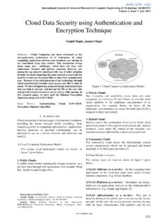
4 Automatically. Thus the proposed system, an Intelligent Based on IEEE Low Rate-Wireless Personal Area robot using Zigbee saves human live and reduces manual Network standard, the Zigbee standard has been proposed to interconnect simple, low rate and battery powered wireless Manuscript received April, 2014. devices needs of low-cost, low-power, wireless sensor Ankita Patel Pursing bachelor of Engineering Sabar Institute of Technology for girls, Gujarat technology University, India. Her field of networks It can send data up to 30m and it has low power interest is Robotics, power electronics. consumption (1mW for transmitting data). Xbee works in Kinjal Chaudhari Pursing bachelor of Engineering Sabar Institute of Technology for girls, Gujarat technology University, India. Her field of GHz frequency and offers Application Programming three interest is networking. modes of operation; AT mode, following the command Dattukumar Patel completed his bachelor of engineering in electronics &.
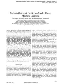
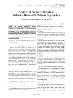
5 Communication in , Bhandu, Gujarat, India. He also completed his mode. Secondly, it can identify the source address of each degree in Digital Communication in Rajasthan Technical University, kota, India. The author has published many technical papers in various international journals. Currently he is working as an Assistant Professor in Electronics & Communication department. In Sabar Institute of Technology for Girls. His field of interest is Robotics, Core Electronics, Communication, High voltage and Power electronics. ISSN: 2278 1323 All Rights Reserved 2014 IJARCET 1058. International Journal of Advanced Research in Computer Engineering & Technology (IJARCET). Volume 3 Issue 4, April 2014. Figure 3: Interfacing between Touch screen µ controller Figure 1: The ZigBee firmware model[1] This causes a change in the electrical current which is registered as a Touch event and sent to the controller for processing. ayers uniformly coated with a transparent resistive material and separated by an airgap.
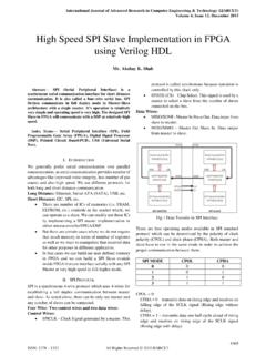
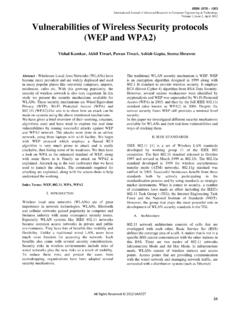
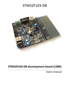
6 Electrodes placed along the edges of the layers provide a means for exciting and monitoring the Touch screen . C. L293D. L293D is a dual H-bridge motor driver integrated circuit (IC). Motor drivers act as current amplifiers since they take a Figure 2: ZigBee Module API Data Frame low current control signal and provide a higher current. The motor operations of two motors can be controlled by input packet and thirdly, it will receive update on the transmission logic at pins 2 & 7 and 10 & 15. Input logic 00 or 11 will stop status whether it is successful or fail. The data frame for API the corresponding motor. Logic 01 and 10 will rotate it in operation is shown in figure 2. The frame is being divided. clockwise and anticlockwise directions, respectively. A. four-wire resistive Touch screen panel consists of two flexible. B. TOUCHSCREEN SENSOR. Touch screen panel is composed of several layers, the most important of which are two thin, metallic, electrically conductive layers separated by a narrow gap.
7 When an object, such as a finger, presses down on a point on the panel's outer surface the two metallic layers become connected at that point: the panel then behaves as a pair of voltage dividers with connected outputs. Figure 4: Motor Driver section D. RS-232. RS-232 is simple, universal, well understood and supportive. The serial port transmits a '1' as -3 to -25 volts and a '0' as +3. to +25 volts. Devices which use serial cables for their communication are split into two categories. These are DCE. (data communications equipment) and DTE (data terminal equipment.) Data communications equipment is devices such ISSN: 2278 1323 All Rights Reserved 2014 IJARCET 1059. International Journal of Advanced Research in Computer Engineering & Technology (IJARCET). Volume 3 Issue 4, March 2014. as the modem, TA adapter, plotter etc while data terminal equipment is your computer or terminal. Figure III(b): Receiver section Figure 5: Circuit diagram of level converter Max232. In addition to this, bomb detection, bomb diffusion, gas leakage detection, live are included.
8 In this, the robot can III. METHODLOGY. move through the rugged surfaces also. Video receiver The methodology of this project design can be divided into receives the video signals from camera. There are three two sections; hardware and software implementations. The motor drivers are used in the robot section. They are the first hardware implementation consists of the development of the two motor drivers are used to control the movement of the Touch screen sensor, Zigbee and LCD and also use robot motor. The second motor driver is used to control for intelligent robot while the software implementation focuses the Camera movement in robot . The 12V battery supply is on program of the microcontroller using Proteus given to the motors for moving the robot and also the supply 7(Embedded C). is given to camera. A. Hardware Implementation Microcontroller is a programmable device. A. microcontroller has a CPU in addition to a fixed amount of RAM, ROM, I/O ports and a timer embedded all on a single chip.
9 The fixed amount of on-chip ROM, RAM and number of I/O ports in microcontrollers makes them ideal for many applications in which cost and space are critical[6]. Here we use PIC18F452 and PIC18F452 for transmitting and receiving sections. Figure 2(a), 2(b) shows the operation of this Transmitter and receiver section system. Figure III(c) : Block diagram for transmitter section Figure III(a): Transmitter section ISSN: 2278 1323 All Rights Reserved 2014 IJARCET 1060. International Journal of Advanced Research in Computer Engineering & Technology (IJARCET). Volume 3 Issue 4, April 2014. which it can overcome the Only the imagination can limit the applications of the above proposed system. Though the following are some examples . Robotic vision development, Exploration robots, Can be used for Industry application, Fire fighting robot , Various military applications, Gaming, V. Conclusion This proposed system gives an exposure to design a spy robot that can be used to do multifunction in defense.
10 This proposed design and implementation Touch screen controlled spy robot by using ZigBee technology will be used to control the robot using the Touch screen from certain rang of distance using the ZigBee based wireless communication Figure III(D) : Block diagram for transmitter section multiple flying robot very easilyapplications and extensions. protocol by this method we can easily control the multiple B. Software Implementation flying robot very easily. The software part consists of programming PIC16LF452. microcontroller using PIC C compiler. The scope of programming includes USART communication programming, LCD character module programming and analog to digital converter programming. All of this programming is done using C language. In proteus software we have used virtual terminal instead of zigbee and variable register instead if Touch screen and finally transmitter section REFERENCES. successfully run using LCD display. RXD. LCD1. 1. ZigBee Alliance, ZigBee Specification.