Transcription of TOYOTA tC 2011- HANDS FREE BLU LOGIC Preparation
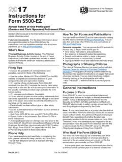
1 TOYOTA tC 2011- HANDS free BLU LOGIC Preparation Page 1 of 12 Issue A: 08/25/10 Item 2 Item 3 Item 5 Item 6 Item 7 Item 8 Item 4 Part #: PT923-00111 NOTE: Part number of this accessory may not be the same as the part number : JBL Audio, Factory NavigationKit Contents: For kits manufactured on or after 19D0, installation kits will include BLU LOGIC Switch Decal. The manufacturing date code is on the part label of the packaging box and is printed as DDMY . Please note that this manufacturing date is per TOYOTA standards and is in the format of DAY-DAY-MONTH-YEAR. Example: 31L8 date on label means 31st, December, 2008 . Hardware ContentItem#Quantity Module21 Main Power Harness31 BLU LOGIC Switch41 Switch Extension Lock Ties72 Adhesive Foam Pad81 Owner s Manual933cm1/4 Wire Split Loom101 BLU LOGIC DecalAdditional Items (may be required)Item#Quantity Sequence of ApplicationItem#Quantity Service Parts (may be required for reassembly)Item#Quantity : Damage to the vehicle may occur.
2 Do not proceed until pro-cess has been complied : A process that must be carefully observed in order to reduce the risk of damage to the SAFETY: Use caution to avoid risk of & EQUIPMENT: Used in Figures to call out the specific tools and equipment recommended for the MARK: This mark highlights a change in installation with respect to previous TORQUE: This mark indicates that torque is related to : Video Available; click to PlayItem 9 Recommended ToolsPersonal & Vehicle ProtectionNotesSafety GogglesSeat CoversFloor CoversSpecial ToolsPanel Clip RemovalSST # 00002-06001-01 Sockets10 mmScrewdriverPhillips, #2 Side CuttersTorque Wrench36 in-lbf ( ) Installation ToolsNotesMasking TapeVDC SuppliedFoam TapeVDC SuppliedSpecial ChemicalsNotesCleanerVDC Approved CleanerGeneral ApplicabilityNote:Item 10 Item 1 TOYOTA tC 2011- HANDS free BLU LOGIC Preparation Page 2 of 12 Issue A: 08/25/10I.
3 Preparation ..1-21. Table Of 22. Content Location ..3II. 4-111. Vehicle 42. Vehicle 43. Interface Module Installation ..54. BLU LOGIC Switch Installation ..75. Microphone Installation ..96. Finalize Installation ..117. Apply BLU LOGIC Decal to Switch ..11 III. Checklist ..121. Accessory Function Checks ..122. Vehicle Function Checks ..12 Accessory Installation Practice (read before installation)Care must be taken when installing this accessory to ensure damage does not occur to the vehicle. The installation of this accessory should follow approved guidelines to ensure a quality guidelines can be found in the Accessory Installation Practices document covers such items as: Vehicle Protection (use of covers and blankets, cleaning chemicals, etc.)
4 Safety (eye protection, checking torque procedure, etc.) Vehicle Disassembly/Reassembly (panel removal, part storage, etc.) Electrical Component Disassembly/Reassembly (battery disconnection, connector removal, etc.)Please see your TOYOTA /Scion/Lexus dealer for a copy of this tC 2011- HANDS free BLU LOGIC Preparation Page 3 of 12 Issue A: 08/25/10 Content Location1 Interface Module2 Wired Microphone3 BLU LOGIC Switch Location TOYOTA tC 2011 - HANDS free BLU LOGICP rocedure Page 4 of 12 Issue A: 08/25/101. Vehicle Preparation (Fig. 1-1)a. Apply parking Protect fender before Remove the negative ( ) battery : Do not touch the positive termi-nal with any tool during removal. d. Using the protective blanket, cover front seat, top of the shift lever and center Place removed vehicle components on a protective blanket.
5 Fig. 1-13. Using a 10mm socket/ratchet, remove four (4) bolts securing the radio (Fig. 1-3).4. Support the radio assembly on a sup-port box (or with other appropriate means) to prevent any damage to the connections as well as preventing scratches to any car panel(s).NOTE: Be careful not to put too much ten-sion on the radio connections when pulling out the Disconnect all connectors and set radio assembly aside. 2. Vehicle Disassemblya. Remove radio Using HANDS or appropriate panel removal tool, disengage the bottom of the radio bezel (Fig. 1-2).NOTE: Apply protective tape to any pry Disconnect any connectors and re-move. Fig. 1-2 Socket (10 mm), RatchetFig. 1-3 Panel Removal ToolSocket (10 mm), Ratchet TOYOTA tC 2011 - HANDS free BLU LOGICP rocedure Page 5 of 12 Issue A: 08/25/103.
6 Interface Module Mount interface : DO NOT remove protective foam wrap from the Insert interlocked wire ties (two ties on each side) into the module as shown in Fig. : Leave about 50 mm of excess wire tie as shown (Insert Image). Fig. 1-4 Fig. 1-5 Fig. 1-6 Side Cutters 2. Loosely mount the interface module on the crossbar (Fig. 1-5).3. Connect main wire harness, micro-phone and BLU LOGIC switch cable to the interface module (Insert Image).NOTE: The Red connector is connected to the matching Red connector on the Tuck the module up and behind the crossbar and securely tighten the wire : BLU LOGIC wire ties in Fig. 1-5 and the remainder of these instructions will be shown in Cut the adhesive foam tape in half (Insert Image).
7 6. Apply the adhesive foam tape to the wire ties and crossbar as shown in the Fig. 1-6. TOYOTA tC 2011 - HANDS free BLU LOGICP rocedure Page 6 of 12 Issue A: 08/25/107. Secure the main harness to the tab on the blower box (Fig. 1-7) 8. Connect main wire harness to match-ing factory radio harness and secure with wire tie (Fig. 1-8).NOTE: AVC-LAN (12 pin) connector may not be present on the vehicle s harness. Wire tie this connector to the harness unconnect-ed, but ALWAYS connect the AVC-LAN (12 pin) connector into the AVC-LAN (12 pin) connector is present on vehicle harness, connect to jumper pro-vided with BLU LOGIC unit. 9. Bundle up the excess main harness and secure it to the vehicle wire harness (Fig.)
8 1-9). Fig. 1-7 Fig. 1-8 Fig. 1-9 Side CuttersTOYOTA tC 2011 - HANDS free BLU LOGICP rocedure Page 7 of 12 Issue A: 08/25/10 Socket (10 mm), Ratchet4. BLU LOGIC Switch Remove lower steering column Turn the steering wheel to access the steering column cover release holes (Fig. 1-10).NOTE: There are two release holes, one on the right and one of the left of the steering column Insert appropriate steering column cover release tool and gently pull down on the Using a 10mm socket/ratchet, remove the two (2) upper bolts securing the knee air bag assembly (Fig. 1-12).3. Carefully remove the airbag assembly and rest it on an appropriate protective : Do not put too much tension on the airbag cable(s). b.
9 Remove knee air bag Using a 10mm socket/ratchet, remove the two (2) lower bolts securing the knee air bag assembly (Fig. 1-11). 10mm Socket/RatchetCover Release ToolFig. 1-10 Fig. 1-11 Fig. 1-12 TOYOTA tC 2011 - HANDS free BLU LOGICP rocedure Page 8 of 12 Issue A: 08/25/10 c. Remove left knee trim Using HANDS or appropriate trim removal tool, disengage the left knee trim panel and remove (Fig. 1-13).NOTE: Apply protective tape to any pry area. d. Route BLU LOGIC cable (highlighted in blue).1. Route switch extension cable and microphone towards the opening of the knee panels and behind LH round metal reinforcement (Fig. 1-14). Panel Removal ToolPanel Removal ToolFig. 1-13 Fig. 1-14 Fig. 1-152.
10 Loosely secure the switch and micro-phone cable to the existing wire loom with two (2) wire ties pointed out by the red arrow (Fig. 1-15).3. Loosely secure the remainder of the switch extension cable with three (3) wire ties as shown (Fig. 1-15). TOYOTA tC 2011 - HANDS free BLU LOGICP rocedure Page 9 of 12 Issue A: 08/25/104. Position the switch connector about 4-5 inches from the white connector plug (Red Arrow, Fig. 1-16).5. Tighten the three (3) left wire : The wire ties pointed out by the red arrows in Figure 1-15 will be tighten once the microphone wire is routed. Fig. 1-16e. Mount BLU LOGIC Remove the far right blank knock-out and mount the BLU LOGIC switch with the solid arrow pointing up (Fig. 1-17).