Transcription of Trailblazer 325 - Miller
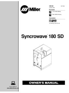
1 Trailblazer 325 ProcessesDescriptionTIG (GTAW) WeldingPulse TIG (GTAW) WeldingStick (SMAW) WeldingMIG (GMAW) WeldingFlux Cored (FCAW)Engine Driven Welder/GeneratorOM-277904A2017 01 Air Plasma Cutting and Gougingwith Spectrum UnitAir Carbon Arc (CAC-A) Cuttingand GougingFile: Engine DriveFor product information,Owner s Manual translations,and more, Electric manufactures a full lineof welders and welding related information on other quality Millerproducts, contact your local Miller distributor to receive the latest fullline catalog or individual specification sheets. To locate your nearestdistributor or service agency call 1-800-4-A- Miller , or visit us on the you and congratulations on choosing Miller . Now you can getthe job done and get it done right.
2 We know you don t have time to doit any other s why when Niels Miller first started building arc welders in 1929,he made sure his products offered long-lasting value and superiorquality. Like you, his customers couldn t afford anything less. Millerproducts had to be more than the best they could be. They had to be thebest you could , the people that build and sell Miller products continue thetradition. They re just as committed to providing equipment and servicethat meets the high standards of quality and value established in Owner s Manual is designed to help you get the most out of yourMiller products. Please take time to read the Safety precautions. Theywill help you protect yourself against potential hazards on the ve made installation and operation quickand easy.
3 With Miller you can count on yearsof reliable service with proper if for some reason the unit needs repair,there s a Troubleshooting section that willhelp you figure out what the problem is. Theparts list will then help you to decide theexact part you may need to fix the and service information for yourparticular model are also is the first weldingequipment manufacturer inthe to be registered tothe ISO 9001 Quality as hard as you do every power source fromMiller is backed by the mosthassle-free warranty in Miller to YouMil_Thank 2009 09 TABLE OF CONTENTSSECTION 1 SAFETY PRECAUTIONS READ BEFORE Symbol Arc Welding Engine Compressed Air Additional Symbols For Installation, Operation.
4 And California Proposition 65 Principal Safety EMF 2 CONSIGNES DE S CURIT LIRE AVANT Signification des Dangers relatifs au soudage l Dangers existant en relation avec le Dangers li s l air comprim Dangers suppl mentaires en relation avec l installation, le fonctionnement et la Proposition californienne 65 Principales normes de s curit Informations relatives aux 3 Additional Safety Symbols And Miscellaneous Symbol 4 Serial Number And Rating Label Environmental Dimensions, Weights, And Operating Duty Fuel Consumption Stick Volt-Ampere MIG Volt-Ampere TIG Volt-Ampere 5 Installing Grounding Generator To Truck Or Trailer Installing Exhaust Engine Prestart Connecting Or Replacing The Weld Output Connecting To Weld Output Selecting Weld Cable Sizes* Remote Receptacle 6 OPERATING Front Panel Controls (See Section 6-2) Description Of Front Panel Controls (See Section 6-1)
5 Cold Weather Engine Process/Contactor Switch, Engine Auto Speed, And Arc Stick Start Procedure Scratch Start Lift-Arc TIG With Auto-Crater And Auto-Stop Remote Voltage/Amperage OF CONTENTSSECTION 7 OPERATING AUXILIARY Generator Power Receptacles And supplementary GFCI Receptacle Information, Resetting And Optional Excel Simultaneous Weld And Wiring Instructions For Optional 240 Volt, Single-Phase Plug (NEMA 14-50P) 8 MAINTENANCE & Maintenance Routine EFI System And Servicing Servicing Air Servicing Optional Spark Changing Engine Oil, Oil Filter, and Fuel Overload Engine Speed Welding Generator Power Engine 9 PARTS Recommended Spare 10 ELECTRICAL 11 GENERATOR POWER PARTS LIST Available at Page 1 SECTION 1 SAFETY PRECAUTIONS READ BEFORE USINGrom_2015 09 Protect yourself and others from injury read, follow, and save these important safety precautions and operating Symbol UsageDANGER!
6 Indicates a hazardous situation which, ifnot avoided, will result in death or serious injury. Thepossible hazards are shown in the adjoining symbolsor explained in the a hazardous situation which, if not avoided,could result in death or serious injury. The possiblehazards are shown in the adjoining symbols or ex-plained in the Indicates statements not related to personal injury. Indicates special group of symbols means Warning! Watch Out! ELECTRICSHOCK, MOVING PARTS, and HOT PARTS hazards. Consult sym-bols and related instructions below for necessary actions to avoid Arc Welding HazardsThe symbols shown below are used throughout this manualto call attention to and identify possible hazards.
7 When yousee the symbol, watch out, and follow the related instructionsto avoid the hazard. The safety information given below isonly a summary of the more complete safety informationfound in the Safety Standards listed in Section 1-7. Read andfollow all Safety qualified persons should install, operate, maintain, andrepair this operation, keep everybody, especially children, live electrical parts can cause fatal shocksor severe burns. The electrode and work circuit iselectrically live whenever the output is on. The inputpower circuit and machine internal circuits are alsolive when power is on. In semiautomatic or automat-ic wire welding, the wire, wire reel, drive roll housing,and all metal parts touching the welding wire areelectrically live.
8 Incorrectly installed or improperlygrounded equipment is a SHOCK can kill. Do not touch live electrical parts. Wear dry, hole-free insulating gloves and body protection. Insulate yourself from work and ground using dry insulating matsor covers big enough to prevent any physical contact with the workor ground. Do not use AC output in damp areas, if movement is confined, or ifthere is a danger of falling. Use AC output ONLY if required for the welding process. If AC output is required, use remote output control if present onunit. Additional safety precautions are required when any of the follow-ing electrically hazardous conditions are present: in damplocations or while wearing wet clothing; on metal structures suchas floors, gratings, or scaffolds; when in cramped positions suchas sitting, kneeling, or lying; or when there is a high risk of unavoid-able or accidental contact with the workpiece or ground.
9 For theseconditions, use the following equipment in order presented: 1) asemiautomatic DC constant voltage (wire) welder, 2) a DC manual(stick) welder, or 3) an AC welder with reduced open-circuit volt-age. In most situations, use of a DC, constant voltage wire welderis recommended. And, do not work alone! Disconnect input power or stop engine before installing orservicing this equipment. Lockout/tagout input power according toOSHA 29 CFR (see Safety Standards). Properly install, ground, and operate this equipment according toits Owner s Manual and national, state, and local codes. Always verify the supply ground check and be sure that inputpower cord ground wire is properly connected to ground terminal indisconnect box or that cord plug is connected to a properlygrounded receptacle outlet.
10 When making input connections, attach proper grounding conduc-tor first double-check connections. Keep cords dry, free of oil and grease, and protected from hot metaland sparks. Frequently inspect input power cord and ground conductor fordamage or bare wiring replace immediately if damaged barewiring can kill. Turn off all equipment when not in use. Do not use worn, damaged, undersized, or repaired cables. Do not drape cables over your body. If earth grounding of the workpiece is required, ground it directlywith a separate cable. Do not touch electrode if you are in contact with the work, ground,or another electrode from a different machine. Use only well-maintained equipment. Repair or replace damagedparts at once.