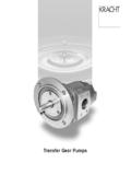
Transcription of Transfer Gear Pumps KF 4.. - Process Pump Sales
1 Transfer gear PumpsKF 4 .. 80 KRACHT GmbH Postbox 1420/1440 D-58774 Werdohl Phone 0049 (23 92 ) 935-0 Fax 0049 (23 92 ) 935 209 Internet: e-mail: from A ZApplicationsSuitable fluidsAdhesivesAntifreezeBore oilsCutting oilsDiesel oilsDrawing compoundEmulsionsFuel oils, L, EL, HGear oilsGreaseHardening oilsHeat Transfer mediaHeavy oilsHydraulic fluidsIsocyanateLubricating oilsLacquersMotor oilsNitrocelluloseTechnical dataPageContents ..2 Applications ..2 Descriptions ..3 Characteristics ..4 Technical data, Type code ..5 Tables: Discharge flow and power consumption6 Determination of power consumption ..7 Dimension sheetsContentsPageFlange-mounting Pumps .. Nom. displacement 4 258 Flange-mounting Pumps .. Nom. displacement 32 809 Foot mounted pump.
2 Nom. displacement 4 2510 Foot mounted pump .. Nom. displacement 32 8011 Flange-mounting Pumps in cast ironNom. displacement 4 2512 Flange-mounting Pumps in cast ironNom. displacement 32 8013 Accessory couplings ..14 Motor-Pump Assemblies .. Nom. displacement 4 2515 16 Motor-Pump Assemblies .. Nom. displacement 32 8017 18 Accessory connections ..19 PaintParaffinsPlasticsPolyolsPrinting inksProcessing oilsResinsRolling oilsWaste oilsWaxesCentrifuge constructionCoating machinesCompressorsEngine construction Filling stationsFilter systemsGenerator constructionHeat Transfer systemsHeavy electrical machinesLubricant manufacturersLubricating oil systemsMachine-building industryMachine toolsManufacture of apparatusMarine engine constructionMetal-forming machinesMetering systemsPaint industryPlain metal bearing productionPrinting machinesPUR machineryRefrigeratorsRubber and tire manufacturingTank plant constructionTransmission buildingTurbine constructionVacuum machineryWaste oil - disposal- transport- treatmentKRACHT GmbH Postbox 1420/1440 D-58774 Werdohl Phone 0049 (23 92 )
3 935-0 Fax 0049 (23 92 ) 935 209 Internet: e-mail: featuresKF gear Pumps are used for pumping a wide variety gear Pumps are distinguished especially by their widerange of variants which are assembled as required on themodular principle and also permit subsequent Pumps are also suitable for media with low standard housing sections are of grey cast iron. The gear units are manufactured from high-strength case-hardening steel, hardened and mounted in specialmulti-compound plain bearing standard drive shaft is sealed by rotary shaft lip-type pump sizes incorporate helical tooth system. This feature, combined with special gear geometry, results in extremely low noise levels and reduced pressure : Sealing of the drive shaft Rotary shaft lip-type seal Double rotary shaft lip-type seal (Quench) Mechanical seal Outboard bearing to take up input drive-side radial load Pressure relief valve as safety valve for pump and system Uniform discharge flow direction with changing directionof rotation by means of flange-mounting valve combi-nation (universal device).
4 Special designVarious shafts ends and gear units, as well as flange mounted versions, bearing alternatives, multi-stage pumpcombinations for your special application are available Sales engineers will be pleased to advise : Connecting flanges Couplings Bell housingsOperating notes The fluids should ensure a certain minimum lubricatingproperties, should not contain solids and should bechemically compatible. Avoid dry operation. The Pumps may only be operated in the specified direction of rotation, as otherwise the shaft seal will be destroyed. In order to prevent excessive overpressure, a safety valveshould be provided in the system or on the pump. The pressure relief valve attached to the pump may onlybe used as safety valve for short-term operation.
5 To drain off a partial discharge flow over a prolongedperiod, a separate pressure relief valve with return linemust be inserted in the reservoir. A separate pressure relief valve with return line to thereservoir must be foreseen, if a partial discharge flow has to be drained over a prolonged of rotation:The following should be notedfor direction of rotation: when looking at the pumpshaft end, the direction ofpumping is from left toright if the shaft rotatesclockwise. when looking at the pumpshaft end, the direction ofpumping is from right toleft if the shaft running ccwsuction sidepressure sidepump running cwsuction sidepressure sidepump running ccwsuction sidepressure sidepump running cwsuction sidepressure sideWithout pressure relief valveWith pressure relief valveCharacteristicsGetriebeLagerbuchseL agerdeckelGeh useAntriebswellenendeWellendichtung14 Nominal displacement cm3Vg= 4/5 cm332/40/50/63/80 cm3 Operating pressureSuction sidepe bar (vacuum)briefly on startup barwith universal model restriction pe minpe max.
6 1 bar for NBR- and FKM rotary shaft lip-type seal2 bar for PTFE-lip-type seal10 bar for mechanical seal (higher pressures on request)Pressure sidepn=25 bar (higher pressures on request)Speed of rotationsNominal size 4 .. 80 200 .. 3000 1/minViscosity = 12 .. 20,000(dependent on pressure and speed of rotations)Drive shaft endShaft sealHousingGear unitPlain bearing bushesEnd coverDirection of rotations:cw or ccwcw and ccwMounting type:flange DIN ISO 3019 Drive shaft end:ISO R 775 connectionNominal size :Whitworth pipe threadNominal size :SAE flangeFluid temperature m min= -10 C m max=90 C for NBR lip-type shaft seal = 150 C for FKM lip-type shaft seal = 200 C for PTFE lip-type seal =150 C for GLRD with FKM aux. seals= 200 C for GLRD with PTFE aux.
7 SealsAmbient temperature u= -20 .. 60 CMounting position: optional(for exception, see Universal unit)Discharge flow:see Table page 7 Drive power:see Table page 7 and 8 KRACHT GmbH Postbox 1420/1440 D-58774 Werdohl Phone 0049 (23 92 ) 935-0 Fax 0049 (23 92 ) 935 209 Internet: e-mail: dataType codeProduct nameNominal sizeDirection of rotationsMountingValve typeFDIN flange without outboard bearingGDIN flange with outboard bearingWMounting angle without outboard bearingXMounting angle with outboard bearingRCW LCCW UuniversalB CW and CCWD 15 adjustable from 0 15 barD 25 adjustable from 15 25 barMeans:Pump with Vg 40 cm3running clockwiseDIN flange without outboardbearing NBR lip-type seal with pressure relief valve 0-15 lip-type seal NBR2lip-type seal FKM3 lip-type seal PTFE4 double lip-type seal PTFE5mechanical seal with FKM aux.
8 Seals6 mechanical seal with PTFE aux. seals7double radial shaft sealing ring FKMSeal typeKF40 R F 1- D 15 RemarkOperating pressurepb= perm. sustained pressurePermissible load only forversion with outboard centre of shaft certain operating conditions, the minimum or maximum characteristicsshould not be example, the max. operating pressure is notpermissible in combinationwith low speed and low such limit ranges, please consult GeometricalOperatingMaximumSpeed rangePermissiblesizedisplacementpressure pressureload(n = 1500 1/min)Vgpbpmax nminnmaxFradial cm3barbar1/min1 GmbH Postbox 1420/1440 D-58774 Werdohl Phone 0049 (23 92 ) 935-0 Fax 0049 (23 92 ) 935 209 Internet: e-mail: GmbH Postbox 1420/1440 D-58774 Werdohl Phone 0049 (23 92 ) 935-0 Fax 0049 (23 92 ) 935 209 Internet: e-mail.
9 ConsumptionTable 2 Speed n = 1450 1/minTable 1 Speed n = 950 1/minDischarge flow Q in l/minPower consumption P in KWPower consumption P in KWDischargeQ in l/minThe ratings refer to amineral oil with a viscosity of 34 mm2 pbin barNominal sizePressure pbin of error for the flowQ +2,5 % .. 5 % of the tabular value. For viscosity < 30 mm2/s,take a reduction of the ratedflow Q into output of the drivemotor should be selected20 % higher than tabularvalue viscosity > 100 mm2/s, anincrease in the required poweris necessary, in this case proceedas per description on page pbin barNominal sizePressure pbin GmbH Postbox 1420/1440 D-58774 Werdohl Phone 0049 (23 92 ) 935-0 Fax 0049 (23 92 ) 935 209 Internet: e-mail: consumptionDrehzahlViskosit tsfaktorn1/minkWl/minkinematische Viskosit tnf f Conversion factors1bar^= psi1^= [ ]1^= [US] of power consumptionP1Pu =Ptab + f QP1Pu=pump power consumption (kW)Ptab=power consumption per table (kW)n=speed (1/min)dependent on viscosity!
10 F =viscosity factorsee diagramQ=discharge flow (l/min) where Q =Vg=geometrical displacement (cm3)2 3 4567892 3 4567892 3 456789 Diagram: n, f = f( )Note:To determine the power consumption, always takethe max. operating viscosity at starting stateinto power of the drivemotor should be selected20 % higher than the []n1450 Example: Pump-type KF 80 Viscosity =3000 mm2/sOperating pressurep=15 baratPtab= kWn=500 1/minf =0,017Q=40 l/minbecomesP1pu = P1Pu = kWMotor power output: P2 Mot= P1Pu= kWSelect helical geared motor withP= kWn=500 1/minSpeed recommendationKinematic viscosity mm2/s <300300500100020003000600010000200003000 0 1500 1250 1000750600500400300200100 Speed nmax1/minkWl/min( + 40)kW 5001450Vg n1000mm2/s 102103104105 SpeedViscosityKinematic viscosityFlange-mounting pumpF3397J 63 1425164ab8016108559514,2j6h880F339716108 5580100J19514,2 63 1480j6h825164abKF Flange-mounting version with pressure relief valveKF Flange-mounting versionNominalSuction andWeight in kgsizepressure 3 deepKRACHT GmbH Postbox 1420/1440 D-58774 Werdohl Phone 0049 (23 92 ) 935-0 Fax 0049 (23 92 ) 935 209 Internet: e-mail.