Transcription of Transfer Switches - Eaton
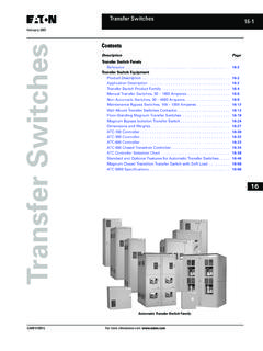
1 Transfer Switches Technical Data TD01602016E New Information Contents Transfer Switch Equipment Product Description .. 2 Application Description .. 2 Product Selection.. 4 Manual Transfer Switches , 30 1000 Amperes .. 6 Non-Automatic Switches , 30 4000 Amperes .. 9 Maintenance Bypass Switches , 100 1000 Amperes .. 12 Automatic (Wall Mount) Transfer Switches .. 13 Floor-Standing Magnum Transfer Switches .. 19 Magnum Bypass Isolation Transfer Switch .. 24 Dimensions and Weights.. 27 ATC-100 Controller.. 31 ATC-300 Controller.. 32 ATC-600 Controller.. 33 ATC-800 Closed Transition Controller .. 34 ATC Controller Selection Chart .. 38 Standard and Optional Features for Automatic Transfer Switches .. 47 Magnum Closed Transition Transfer Switch with Soft Load .. 59 ATC-5000 Specifications .. 67 Automatic Transfer Switch Family 2 Eaton CORPORATION Cutler-Hammer Transfer Switches Technical Data TD01602016E Effective: August 2006 Transfer Switch EquipmentAutomatic Transfer Switches Automatic Transfer Switch Family Product Description Eaton s Cutler-Hammer Automatic Transfer Switches are reliable, rugged, versatile and compact assemblies for transferring essential loads and electrical distribution systems from one power source to Switches can be supplied in separate enclosures for stand-alone applications or can be supplied as an integral component in the following equipment: Magnum DS Switchgear.
2 Pow-R-Line Switchboards. Motor Control Centers. detailed information on the aforementioned equipment, please see Eaton s 14th edition of the Consulting Application Guide . Note: For information on Transfer Switch Panels, refer to Section 4 of the Distribution Products and Services catalog Advanced Residential Products. Application Description A Transfer switch is a critical component of any emergency or standby power system. When the normal (preferred) source of power is lost, a Transfer switch quickly and safely shifts the load circuit from the normal source of power to the emergency (alternate) source of power. This permits critical loads to continue running with minimal or no outage. After the normal source of power has been restored, the re- Transfer process returns the load circuit to the normal power Switches are available with different operational modes including: Manual. Non-automatic. Automatic. Bypass isolation. Soft load.
3 Maintenance power switching operation of Transfer Switches may be separated into the three (3) key categories of: Open Transition Break-before-Make operation. Closed Transition Make-before-Break operation. Closed Transition Soft Load Both sources are paralleled and can remain so three (3) basic components of a Transfer switch are: Power switching device to shift the load circuits to and from the power source. Transfer Logic Controller to monitor the condition of the power sources and provide the control signals to the power switching device. Control power source to supply operational power to the controller and switching device. Typical Applications All Eaton Transfer Switches are designed to meet the requirements set forth by UL 1008, however, all Transfer Switches are not created equal. You can be assured of safe and reliable operation from all types of Transfer Switches that Eaton offers. TABLE 1. UL 1008 ENDURANCE TESTINGTABLE 2. UL 1008 LIFE EXPECTANCY UL 1008 Endurance Testing The importance of specifying a UL 1008 Transfer switch can be seen in Table 1.
4 When specifying any UL 1008 Transfer switch, you can be assured the switch has met and passed the following endurance testing. UL 1008 Life Expectancy Transfer switch applications typically require a plant exerciser once a week or once a month. Table 2 demonstrates the life expectancy operating the UL 1008 switch once a week for the life of the switch. ATS RATING(AMPERES)RATE OFOPERATIONPER MINUTEWITHCURRENTWITHOUTCURRENTTOTAL 0 30016000 6000301 40014000 4000401 801200010003000801 ATS RATING(AMPERES)MINIMUM OPERATIONSPER YEARLIFE EXPECTANCY IN YEARSWITHCURRENT APPLIEDWITHOUTCURRENT APPLIED 0 30052115115301 400527676401 800523857801 16005228571601 5000521957 Eaton CORPORATION Cutler-Hammer Transfer Switches Technical Data TD01602016E Copyright 2006 3 Utility Generator Transfer Switches are traditionally applied between a utility and a generator set for emergency and standby power systems. FIGURE 1. STANDARD APPLICATION UTILITY GENERATOR Generator Generator Transfer Switches are sometimes applied between two generator sets for prime power use, often in remote installations.
5 In such applications, source power is periodically alternated between the generator sets to equally share run-time. FIGURE 2. STANDARD APPLICATION GENERATOR GENERATOR Service Entrance Rated Transfer Switches Modifying the molded case switch in the Transfer switch by adding trip units and optional ground fault, along with adding the service entrance option eliminates the need for separate upstream discon-nect devices and their respective power interconnections. This means the Automatic Transfer Switch (ATS) is installed directly at the point of service entrance, saving valuable space and cost. FIGURE 3. SERVICE ENTRANCE RATED Transfer Switches Built-in Protection All Eaton Molded Case Switches are self protected, such that under extreme fault conditions, the switch will open before destroy-ing itself. This feature allows Eaton to offer Maintenance Free Contacts on the molded case Transfer switch. The molded case Switches have instantaneous magnetic trip units installed in each switch.
6 These trips are not accessible once installed by the factory to eliminate field tapering. The trips are set to a minimum of 12 to 15 times the rated current of the molded case device, well above any coordination set points. This means they will not interfere with the normal operation of the distribution system and will only trip if something is very wrong. FIGURE 4. BUILT-IN PROTECTION Magnetic Trip 12 x frame ServiceGGeneratorBreakerLoadATSS erviceDisconnectUtility ServiceTypical Transfer Switch InstallationTransfer Switch Installation RatedFor Service Entrance400 FLA x = 500 Ampere BreakerCompare 400 Ampere ATS and 500 Ampere LD BreakerTime(Min.) 5 1 2 3 4 5 6 7 8 9 10 Breaker Ok400 ATS Will Only Trip at 7200 Amperes 100% Rated Device per UL 1008 Breaker TripsATS Ok ATS Trips500 Ampere HLD BreakerCurrent x 1000 Misconception: Breaker Type Switches Susceptible to Nuisance : 400 Ampere ATS With 500 Ampere T/M BreakerReality: Upstream Breaker Will Trip Before ATS MCS Trips When Overcurrent is <7200 A 4 Eaton CORPORATION Cutler-Hammer Transfer Switches Technical Data TD01602016E Effective: August 2006 Product Selection TABLE 3.
7 Transfer SWITCH PRODUCT FAMILY Key: DO = DrawoutFM = Fixed MountedMPB = Magnum Power BreakerMPS = Magnum Power SwitchMCB = Molded Case BreakerMCS = Molded Case Switch DESCRIPTIONTRANSFER SWITCH EQUIPMENT CATALOG NUMBERING SYSTEMTYPEORIENTATION LOGICFRAMESWITCHPOLESAMPERES VOLTAGEENCLOSURE LISTING Manual (600 Vac)(30 1000 A)MT = ManualRefer to Page 6 H = HorizontalV = VerticalX = No LogicMolded Case DeviceFD = 30 150 AKD = 150 300 ALD = 400 600 AMD = 600 800 ANB = 800 1000 AFixed MountA = FM, N(MCS)E(MCS)B = FM, N(MCB)E(MCB)C = FM, N(MCB)E(MCS)D = FM, N(MCS)E(MCB)2 = 2-Poles3 = 3-Poles4 = 4-Poles0030 = 30 A0070 = 70 A0100 = 100 A0150 = 150 A0225 = 225 A0300 = 300 A0400 = 400 A0600 = 600 A0800 = 800 A1000 = 1000 AE = 600 V 60 HzK = OpenS= NEMA 1J= NEMA 12R= NEMA 3RL= NEMA 4D= NEMA 4XU = UL ListedR = UL RecognizedX = No ListingNon-Automatic(600 Vac)(30 4000 A)NT = Non-Auto-maticRefer to Page 9 H = HorizontalV = VerticalE = Electro-mechanicalMolded Case DeviceFD = 30 150 AKD = 150 300 ALD = 400 600 AMD = 600 800 ANB = 800 1000 AInsulated Case Device (Magnum)MG = 600 4000 AFixed MountA = FM, N(M/MPS)E(M/MPS)B = FM, N(M/MPB)E(M/MPB)C = FM, N(M/MPB)E(M/MPS)D = FM, N(M/MPS)E(M/MPB)Drawout MountE = DO, N(MPS) E(MPS)F = DO, N(MPB) E(MPB) G = DO, N(MPB) E(MPS) H = DO, N(MPS) E(MPB)2 = 2-Poles3 = 3-Poles4 = 4-Poles(4-Poles 3000 AMaximum)
8 0030 = 30 A0070 = 70 A0100 = 100 A0150 = 150 A0225 = 225 A0300 = 300 A0400 = 400 A0600 = 600 A0800 = 800 A1000 = 1000 A1200 = 1200 A1600 = 1600 A2000 = 2000 A2500 = 2500 A3000 = 3000 A4000 = 4000 A5000 = 5000 AA= 120 V 60 HzB= 208 V 60 HzE= 600 V 60 HzG= 220 V 50/60 Hz H= 380 V 50 HzK= 600 V 50 HzM= 230 V 50 HzN= 401 V 50 HzO= 415 V 50 HzW= 240 V 60 HzX= 480 V 60 HzZ= 365 V 50 HzK= OpenS= NEMA 1R= NEMA 3RJ= NEMA 12L= NEMA 4D= NEMA 4X(J, L and D 65 kAIC, 1200 A andBelow Only)U = UL ListedR = UL RecognizedX = No ListingMaintenanceBypass(600 Vac)(100 1000 A)MB = MaintenanceBypassRefer to Page 12 H = HorizontalE = Electro-mechanicalMolded Case DeviceFD = 100 150 AKD = 150 300 ALD = 400 600 AMD = 600 800 ANB = 800 1000 AFixed MountA=FM,N(MCS)E(MCS)2 = 2 Poles3 = 3 Poles4 = 4 Poles0100 = 100 A0150 = 150 A0225 = 225 A0300 = 300 A0400 = 400 A0600 = 600 A0800 = 800 A1000 = 1000 AA= 120 V 60 HzB= 208 V 60 HzE= 600 V 60 HzG= 220 V 50/60 HzH= 380 V 50 HzK= 600 V 50 HzM= 230 V 50 HzN= 401 V 50 HzO= 415 V 50 HzW= 240 V 60 HzX= 480 V 60 HzZ= 365 V 50 HzK= OpenS= NEMA 1J= NEMA 12R= NEMA 3RL= NEMA 4D= NEMA 4XU = UL ListedR = UL RecognizedX = No ListingAutomatic(Wall-Mount)(600 Vac)(30 1000 A)AT = Auto-maticRefer to Page 13 H = HorizontalV = Vertical3= ATC-300I= ATC-600 Molded Case DeviceFD = 30 200 AKD = 150 300 ALD = 400 600 AMD = 600 800 ANB = 800 1000 A(FD = 200 A Available on ATH3 Only)Fixed MountA=FM, N(MCS)E(MCS)B=FM, N(MCB)E(MCB)C=FM, N(MCB)E(MCS) D=FM, N(MCS)E(MCB)
9 2 = 2-Poles3 = 3-Poles4 = 4-Poles0030 = 30 A0070 = 70 A0100 = 100 A0150 = 150 A0200 = 200 A0225 = 225 A0300 = 300 A0400 = 400 A0600 = 600 A0800 = 800 A1000 = 1000 AA= 120 V 60 HzB= 208 V 60 HzE= 600 V 60 HzG= 220 V 50/60 HzH= 380 V 50 HzK= 600 V 50 HzM= 230 V 50 HzN= 401 V 50 HzO= 415 V 50 HzW= 240 V 60 HzX= 480 V 60 HzZ= 365 V 50 HzK= OpenS= NEMA 1J= NEMA 12R= NEMA 3RL= NEMA 4D= NEMA 4XU = UL ListedR = UL RecognizedX = No ListingAutomatic (Free Standing) (600 Vac)(600 5000 A)AT = AutomaticRefer to Page 19 V = VerticalI = ATC-600IQ TransferInsulated Case Device (Magnum)MG = 600 5000 AFixed MountA=FM, N(MPS)E(MPS)B=FM, N(MPB)E(MPB)C=FM, N(MPB)E(MPS)D=FM, N(MPS)E(MPB)Drawout MountE=DO, N(MPS)E(MPS)F=DO, N(MPB)E(MPB)G=DO, N(MPB)E(MPS) H=DO, N(MPS)E(MPB)2 = 2 Poles3 = 3 Poles4 = 4 Poles(4 Poles 3000 AMaximum)0600 = 600 A0800 = 800 A1000 = 1000 A1200 = 1200 A1600 = 1600 A2000 = 2000 A2500 = 2500 A3000 = 3000 A4000 = 4000 A5000 = 5000 A(600 A FM only)A= 120 V 60 HzB= 208 V 60 HzE= 600 V 60 HzG= 220 V 50/60 HzH= 380 V 50 HzK= 600 V 50 HzM= 230 V 50 HzN= 401 V 50 HzO= 415 V 50 HzW= 240 V 60 HzX= 480 V 60 HzZ= 365 V 50 HzS= NEMA 1R= NEMA 3RU = UL ListedR = UL RecognizedX = No Listing Eaton CORPORATION Cutler-Hammer Transfer Switches Technical Data TD01602016E Copyright 2006 5 TABLE 3.
10 Transfer SWITCH PRODUCT FAMILY (CONTINUED) Key: DO = DrawoutFM = Fixed MountedMPB = Magnum Power BreakerMPS = Magnum Power SwitchMCB = Molded Case BreakerMCS = Molded Case Switch DESCRIPTIONTRANSFER SWITCH EQUIPMENT CATALOG NUMBERING SYSTEMTYPEORIENTATION LOGICFRAMESWITCHPOLESAMPERES VOLTAGEENCLOSURE LISTING Automatic Closed Transition (<100 ms) (600 Vac) (600 5000 A)CT = ClosedTrans-itionV = VerticalI = ATC-800 ClosedTransitionIQ TransferDevice (Magnum)MG = 600 5000 AFixed MountA=FM, N(MPS)E(MPS) B=FM, N(MPB)E(MPB) C=FM, N(MPB)E(MPS) D=FM, N(MPS)E(MPB) Drawout MountE=DO, N(MPS)E(MPS) F=DO, N(MPB)E(MPB) G=DO, N(MPB)E(MPS) H=DO, N(MPS)E(MPB) 2 = 2-Poles3 = 3-Poles4 = 4-Poles(4 Poles 3000 AMaximum)0600 = 600 A0800 = 800 A1000 = 1000 A1200 = 1200 A1600 = 1600 A2000 = 2000 A2500 = 2500 A3000 = 3000 A4000 = 4000 A5000 = 5000 A(600 A FM Only)A= 120 V 60 HzB= 208 V 60 HzE= 600 V 60 HzG= 220 V 50/60 HzH= 380 V 50 HzK= 600 V 50 HzM= 230 V 50 HzN= 401 V 50 HzO= 415 V 50 HzW= 240 V 60 HzX= 480 V 60 HzZ= 365 V 50 HzS= NEMA 1R= NEMA 3RU= UL 1008 ListedR= UL RecognizedZ= UL 891 ListedX= No ListingBypass Isolation(600 Vac)(800 5000 A)BI = BypassIsolationRefer to Page 24 V = VerticalI = ATC-600 Device (Magnum)MG = 200 5000 ADrawout MountE=DO, N(MPS)E(MPS)F=DO, N(MPB)E(MPB)G=DO, N(MPB)E(MPS) H=DO, N(MPS)E(MPB)2 = 2-Poles3 = 3-Poles4 = 4-Poles(4 Poles 3000 AMaximum)0200 = 200 A1000 = 1000 A1200 = 1200 A1600 = 1600 A2000 = 2000 A2500 = 2500 A3000 = 3000 A4000 = 4000 A5000 = 5000 AA= 120 V 60 HzB= 208 V 60 HzE= 600 V 60 HzG= 220 V 50/60 HzH= 380 V 50 HzK= 600 V 50 HzM= 230 V 50 HzN= 401 V 50 HzO= 415 V 50 HzW= 240 V 60 HzX= 480 V 60 HzZ= 365 V 50 HzS = NEMA 1R = NEMA 3RU= UL 1008 ListedR= UL RecognizedZ= UL 891 ListedX= No ListingClosed Transition Bypass Isolation(<100 ms)(600 Vac)(800 5000 A)