Transcription of Transformer Coupled LC Bandpass Filters - W7ZOI
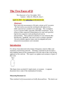
1 Transformer Coupled LC Bandpass Filtersw7zoi, 10 June08, 19 April09 Most of the LC Bandpass Filters that I design and build tend to use capacitors formatching at the ends. Using capacitors produces a non-ambiguous topology that iseasily alternative is to use Transformer coupling. This usually takes theform of a link wound on the inductors. As such, it is a minimum component is a design problem related to this approach. This relates to the less than idealnatureof the magnetic coupling that we see with links wound over appears with powder iron toroids, and is even worse when using air core note describes an experiment I did today with a simple double tuned circuit where Iused link coupling.
2 While not a universal answer to the problem, a simple method ispresented that will allow experimental double tuned circuit is about as simple as a multiple resonator filter can get. Thedesign equations aresummarized in this figure where F is the center frequency of equations for a general double tuned circuit. The k and q values can be changedfor shapes other than experimental filter I considered used inductors consisting of 19 turn of #26 enamelwire on T44-6 toroids. I wound the coils and then measured them with an AADE LCmeter, finding an inductance of inductors have an unloaded Q of about200.
3 The tuning capacitors in the filter , CT, a re 325 pF while the coupling capacitor underlying concept for a Coupled resonator filter is that the filter shape is establishedby establishing the coupling between resonators, the loaded Q of the end sections, and theresonant frequency of all expression for Qendabove provides a value ofabout 49. This is the Q related to the external loading, in this case by the 50 Ohmterminations attached to the parallel resistance, RP, with the value shown willes tablish this Q. Or the link coupling to 50 Ohms will do the how many turns should be on the link?
4 This is the critical value forRPin my filterwas K. If the inductor was wound on a highpermeability ferrite, we couldvalidly assume that impedances would transform inproportion to the square of the , we would take the square root of 3370/50to obtain a turns ratio of The basic inductor uses 19 turns. So that would suggestthat we use a 2 turn link, for 19 , ideal or not, transform with the same ratio for both wewant a 50 Ohm load attached to the link to appear as K Ohms to the other side. So,if we attach a resistor to the 19 turn winding, we should see 50 Ohms whenlooking into the , I attached a resistor to the 19 turn winding and measured theimpedance looking into the link.
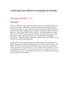
5 This is shown below:A circuit for adjusting the turns on a linkfor loadinga tuned procedure is simple enough. Load the high impedance winding with a suitableresistor. Then look into the link with a return loss bridge driven at the frequency ofinterest. Adjust the circuit for resonance, indicated by thehighest(best)return adjust the number of turns in the link and perhaps the position of the link to obtainthe best match. The resistor is then removed. The Transformer is inserted into the filterand final alignment is simplisticcalculations above suggested a 2 turn link as close to optimum.
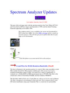
6 But thatwould have described the tight coupling between the link and the coil related to was a powder iron core with permeability of 8, so we would not expect idealcoupling. Accordingly, I measured the input impedance with 2, 3, and 4 turn links. Themeasurements were:NReflection at 171 degrees28+ at-1059+ at-17 degrees95-j20 The 3 turn winding offers thebetter filter was assembled after the end measurements with the transfer function resultshown below:Measured FilterA photo of the filter is shown link Coupled filter .